 ,
, ;Zap为矩形开孔的等效阻抗,Z3为凸面结构的等效阻抗。
摘要 金属腔体外部形状以及内部结构均会对腔体屏蔽效能造成影响。针对内置介质板的异型开孔金属腔体的特点,通过推导异型腔体非连续处等效电路的散射参数,基于电磁拓扑理论和BLT方程,建立平面波照射下凸面结构腔体和阶梯结构腔体屏蔽效能的解析模型,并研究了介质板的位置等对异型腔体屏蔽效能的影响。通过引入开孔位置系数和观测点位置系数,该解析模型可以处理任意位置开孔和任意位置观测点的情况。结果表明:介质板可以有效抑制异型腔体谐振,谐振点附近的屏蔽效能得到显著提高,但是对远离谐振点频域的屏蔽效能影响较小;不同谐振点处存在最佳介质板位置,使得在其取值区间内屏蔽效能达到最大。理论计算结果与全波仿真软件CST的结果有较好的一致性,证实了该文解析模型的有效性。相较于数值计算方法,该解析模型计算效率更高且占用内存更少,对异型腔体的屏蔽设计具有指导意义。
关键词:屏蔽效能 电磁拓扑理论 BLT方程 异型腔体 介质板
随着我国电网的电压等级逐步提升以及电子技术的微型化和集成化程度不断提高,电网中的电子设备面临的电磁环境日益复杂,容易受到电磁干扰的影响[1-6]。为了降低电磁场对设备的干扰,通常在其外部加装金属腔体,起到电磁屏蔽和保护的作用。同时,为了便于腔体外观的美化设计以及内部电路和元件的安装和固定,腔体的结构并不局限于规则的矩形或圆柱形,而存在一些阶梯等结构。理想的金属腔体完全封闭,可以使其内部设备和线路免受任何电磁干扰,然而实际中由于通风散热、走线排线等需求,金属腔体上会开有一些孔缝。孔缝为电磁场耦合进入腔体内部提供了通道,产生谐振,从而降低了腔体的屏蔽效能(Shielding Effectiveness, SE),对其内部电路和器件造成干扰甚至损毁。因此,研究非规则开孔腔体(简称异型开孔腔体)的屏蔽效能问题对于电网的电磁屏蔽和防护具有重要的意义。
开孔腔体的屏蔽效能计算方法主要包括实验方法[7]、数值方法[8]和解析方法[9-23]。实验方法作为验证模型准确性的一种有效手段,由于其成本较高而且耗时较长,因此具有一定的局限性。数值方法擅于对复杂结构的腔体进行精确建模,但是会花费大量的计算时间和内存。相比于数值方法,解析方法虽然局限于简单的腔体结构和材料,但是占用内存更少,计算效率更高,而且便于分析不同参数对腔体屏蔽效能的影响,因此近年来成为开孔腔体屏蔽效能计算的热点方法。解析方法主要包括Bethe小孔耦合理论[9-10]、等效电路法[11-17]和基于电磁拓扑理论的BLT(Baum-Liu-Tesche)方程[18-23]。Bethe小孔耦合理论从电磁场的角度直接推导腔体内的场分布,求解过程比较繁琐,因此研究人员尝试从电路的角度出发来计算腔体的屏蔽效能。基于波导和传输线理论,M. P. Robinson等首先提出一种等效电路方法[11],该方法可以快速、准确地计算平面波照射下矩形金属腔体的屏蔽效能,但是局限于低频、中心开孔、观测点位于孔缝的中心轴线上、平面波垂直入射垂直极化等情况。此后,众多学者逐一解决上述等效电路法的局限性,提出了一系列拓展的等效电路法[12-13]。文献[14]利用拓展的等效电路法对带有凸面结构金属腔体的屏蔽效能进行了研究,并分析了凸面结构参数对屏蔽效能的影响。文献[15]用具有一定厚度、电导率和介电常数的介质板代替复杂的电路板引起的电磁波抑制效应,进而提出并分析装有介质板的开孔矩形金属腔体屏蔽效能的等效电路法。在此基础上,文献[16]研究了装有介质板的带孔阵矩形金属腔体的屏蔽效能。文献[17]研究了加载介质板的双层矩形金属腔体的屏蔽效能。
随着电磁拓扑理论的发展,近年来BLT方程被广泛应用于计算开孔金属腔体的屏蔽效能,适用范围从原始情况(中心开孔、观测点位于孔缝的中心轴线上、平面波垂直入射垂直极化、单层腔体)[18]拓展到任意位置开孔[19]、任意观测点位置[20]、平面波任意角度入射和极化[21]、多层腔体[22]等情况,但是均局限于规则结构腔体。相比于等效电路法仅考虑了由腔体外部经孔缝耦合到内部的单向电磁场,BLT方程将孔缝等效为二端口网络,利用网络的散射矩阵包含双向电磁场耦合,使得腔体屏蔽效能的计算精度显著提高。文献[23]基于BLT方程研究了平面波照射下内置介质板的规则开孔矩形金属腔体的屏蔽效能,并详细分析了介质板的厚度、材料和位置对屏蔽效能的影响,但是仅考虑了中心位置开孔和观测点在开孔的中心轴线上的情况。
本文把文献[23]考虑的规则腔体推广到异型腔体,基于BLT方程提出一种计算内置介质板的异型开孔金属腔体屏蔽效能的解析模型。该解析模型的关键点是推导异型腔体非连续处等效电路的散射参数,相比于规则腔体增加了复杂度。通过引入开孔位置系数和观测点位置系数,该解析模型还可以处理任意位置开孔和任意位置观测点的情况。首先构建内置介质板的异型开孔金属腔体的等效电路模型,其次根据电磁能量的流动情况建立与等效电路模型相对应的信号流图,通过建立节点的散射矩阵方程和管道的传播矩阵方程,得到BLT方程,最后由BLT方程计算得到观测点的电压,进而计算出观测点的屏蔽效能。理论计算结果与CST(computer simulation technology)的仿真结果有较好的一致性,验证了该解析模型的有效性。相比于基于数值方法的CST仿真,该解析模型计算效率更高且占用内存更少,可以为研究和工程技术人员分析此类问题提供参考和指导。
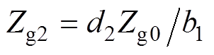
图1为平面波照射下内置介质板的凸面结构开孔金属腔体几何模型。腔体尺寸为a´b1´d,厚度为t,凸面结构的跨度为d2,高度为b2;腔体前壁上有一个尺寸为l´w的矩形开孔,其中心点坐标为(xa, ya, 0),凸面结构左端到开孔的距离为d1;介质板位于腔体内部且完全覆盖腔体横截面,厚度为pd、电导率为s、相对介电常数为er,介质板右端到腔体末端的距离为pr;P0和P(xp, yp, zp)分别表示腔体外部和内部(介于凸面结构右端和介质板左端之间)的观测点,P0到腔体前壁的距离为d0;平面波电场方向沿+y轴,传播方向沿-z轴,即垂直入射和垂直极化。将平面波等效电压为V0=1V的集总电压源,用Vs表示;腔体外部自由空间的特性阻抗和传播常数分别为Z0和k0;腔体内部由波导1(空气介质)、波导2(有损介质)和波导3(空气介质)组成,其特性阻抗和传播常数分别为Zg0和kg0、Zg1和kg1、Zg2和kg2,则可以得到图1的等效电路模型如图2所示。图中,Vs到P0的距离为d01,Vs到开孔的距离为d02,,;Zap为矩形开孔的等效阻抗,Z3为凸面结构的等效阻抗。

图1 平面波照射下内置介质板的凸面结构开孔金属腔体几何模型
Fig.1 Geometry of an apertured metallic enclosure with convex structure embedded a dielectric layer against a plane wave
根据电磁能量的流动情况,给出与图2相对应的信号流,如图3所示。图中,节点J1为腔体外部的观测点,J2为开孔,J3为凸面结构,J4为腔体内部的目标观测点,J5和J6分别为介质板的左端和右端,J7为腔体末端,Ws为凸面型腔体等效电路中的电压源;该信号流由六段虚拟传输线(管道)组成,用Tj(j =1, 2, …, 6)表示,Tj的两端电压分别为Vj1和Vj2。
根据图3得到各节点电压响应的BLT方程为
 (1)
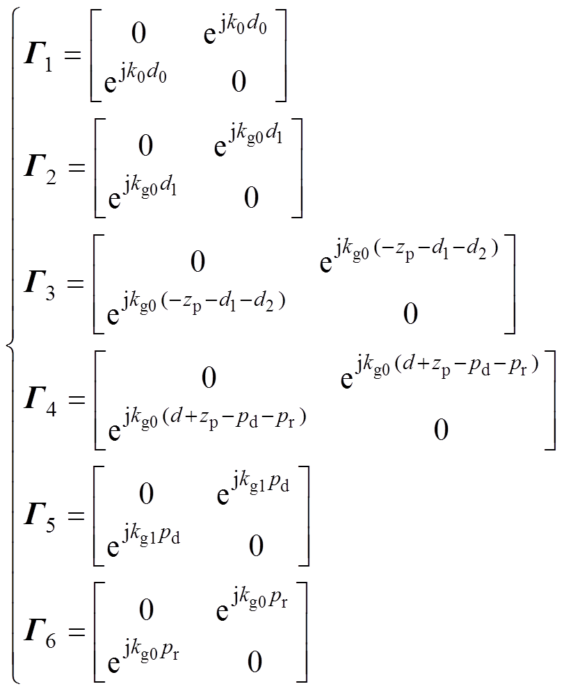
(1)式中,U为12´12阶单位矩阵;V和S分别为按照管道顺序排列的电压向量和激励源向量; 和
和 分别为以节点顺序排列的散射矩阵和以管道顺序排列的传播矩阵,且均为分块对角矩阵,可表示为
图2 平面波照射下内置介质板的凸面结构开孔金属腔体的等效电路
Fig.2 Equivalent circuit of the apertured metallic enclosure with convex structure embedded a dielectric layer against a plane wave
图3 平面波照射下内置介质板的凸面结构开孔金属腔体的信号流
Fig.3 Signal flow graph of the apertured metallic enclosure with convex structure embedded a dielectric layer against a plane wave
 (2)
(2) (3)
(3)
 (4)
(4)
 (5)
(5)式中,r1=0和r7=-1分别为节点J1和J7的反射系数,节点Ji(i =2, …, 6)的散射矩阵分别为
 (6)
(6)
式中, 、
、 、
、 和
和 分别为自由空间、矩形开孔、空气波导和有损介质波导的导纳,且
 ,
, ,
, ,
, ,
, ,
, ,其中,
,其中, ,Zap的表达式[13]为
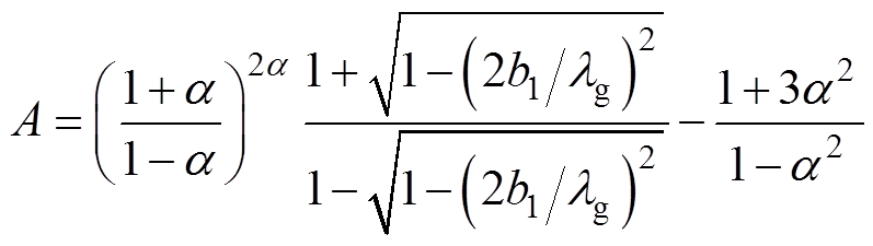
 (7)
(7)式中, ;
; ,l 为自由空间的波长;
 为开孔位置系数,m和n分别为矩形波导内的场分布模式指数。
在TE10模式下,Zg0和Zg1的表达式分别为
 (8)
(8)式中,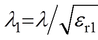 ;
; ,
,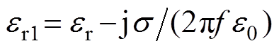 [15],f为频率,e0为真空中的介电常数。
在TE10模式下,Z2[24]和Z3[14]的表达式分别为
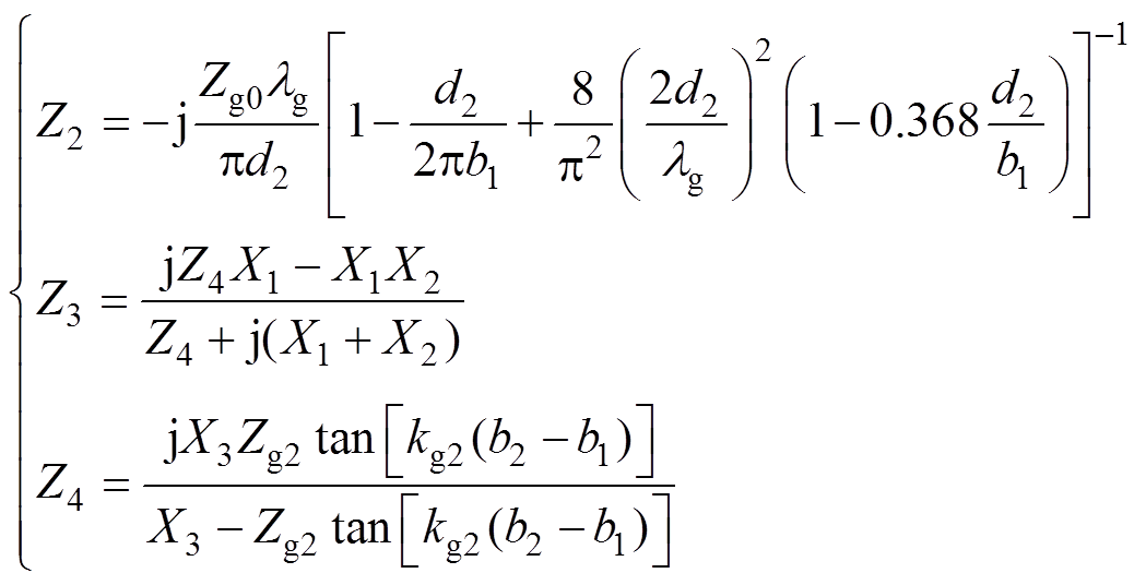 (9)
(9)式中,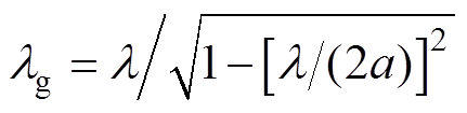 ;
; ;
;
 ;X1、X2和X3的具体表达式见文献[14]。
六段管道的传播矩阵分别为
 (10)
(10)式中,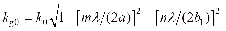 ;
;
 ,
, ,
, 和
和 为介质板中的场分布模式指数。
将式(2)~式(5)代入到式(1),可以得到各节点的电压,其中,V的第七个元素为观测点P(节点J4)的电压,有
 (11)
(11)对于存在多种传播模式(TE模和TM模)的凸面结构腔体,P点的总电压为
 (12)
(12)
式中, 为P点的位置系数。
腔体不存在时,P点的电压为
则P点的屏蔽效能为
 (13)
(13)
当图1中的参数d1=0时,内置介质板的凸面腔体模型变为如图4所示的阶梯模型。左边腔体的尺寸为a´b1´d2,右边腔体的尺寸为a´b2´(d-d2);观测点P1和P2分别位于左右两个腔体中,坐标分别为(xp1, yp1, zp1)和(xp2, yp2, zp2)。
与图4相对应的等效电路模型和信号流分别如图5和图6所示。在图5中, ;
;
 ;
; ,
, ;其他参数保持和图1中的一致。在图6中,节点J1为腔体外部的观测点,J2为开孔,J4为阶梯结构,J3和J5分别为腔体内部的目标观测点P1和P2,J6和J7分别为介质板的左端和右端,J8为腔体末端,Ws为阶梯型腔体等效电路中的电压源;该信号流由七段管道组成,用Tj(j=1, 2, …, 7)表示,Tj的两端电压分别为Vj1和Vj2。
图4 平面波照射下内置介质板的阶梯结构开孔金属腔体的几何模型
Fig.4 Geometry of an apertured metallic enclosure with stepped structure embedded a dielectric layer against a plane wave
类比1.1节中对凸面结构腔体模型的分析过程,当凸面结构变为阶梯结构时,最显著的变化发生在节点的散射参数,其中,图6中节点J4的散射矩阵为
图5 平面波照射下内置介质板的阶梯结构开孔金属腔体的等效电路
Fig.5 Equivalent circuit of the apertured metallic enclosure with stepped structure embedded a dielectric layer against a plane wave
图6 平面波照射下内置介质板的阶梯结构开孔金属腔体的信号流
Fig.6 Signal flow graph of the apertured metallic enclosure with stepped structure embedded a dielectric layer against a plane wave
 (14)
(14)式中, ;
; ,由文献[24]可知

其中
观测点P1(节点J3)和观测点P2(节点J5)的电压分别为
 (15)
(15)
 (16)
(16)类似地,对于存在多种传播模式(TE模和TM模)的阶梯结构腔体,P1点和P2点的总电压分别为
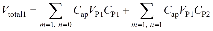 (17)
(17)
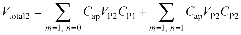 (18)
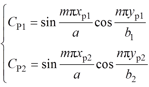
(18)式中,CP1和CP2分别为P1和P2的位置系数。且有
首先考虑图1中的凸面结构腔体,假设腔体尺寸为a´b1´d=300mm´120mm´370mm,厚度为t = 1mm,凸面结构的跨度为d2=100mm,高度为b2= 10mm,凸面结构左端到开孔的距离为d1=30mm;介质板的厚度为pd=10mm,电导率为s =0.22S/m,相对介电常数为er=5,其右端到腔体末端的距离为pr=10mm;观测点P0到等效电压源Vs的距离为d01= 200mm,Vs到开孔的距离为d02=200mm(d0= 400mm);仿真频率为0~1.6GHz。
为验证本文建立的解析模型的有效性,设置了4组仿真实验,不同开孔尺寸和位置、目标观测点位置列于表1,其中仿真1考虑的情况为开孔在腔体前壁中心位置且观测点位于开孔的中心轴线上;仿真2的观测点位于开孔非中心轴线上,其他参数与仿真1保持一致;改变开孔尺寸,仿真3和仿真4为偏心开孔且观测点取任意位置的情况。
表1 验证本文模型凸面结构腔体的仿真参数
Tab.1 Simulation parameters for the verification of the model in this paper for the enclosure with convex structure
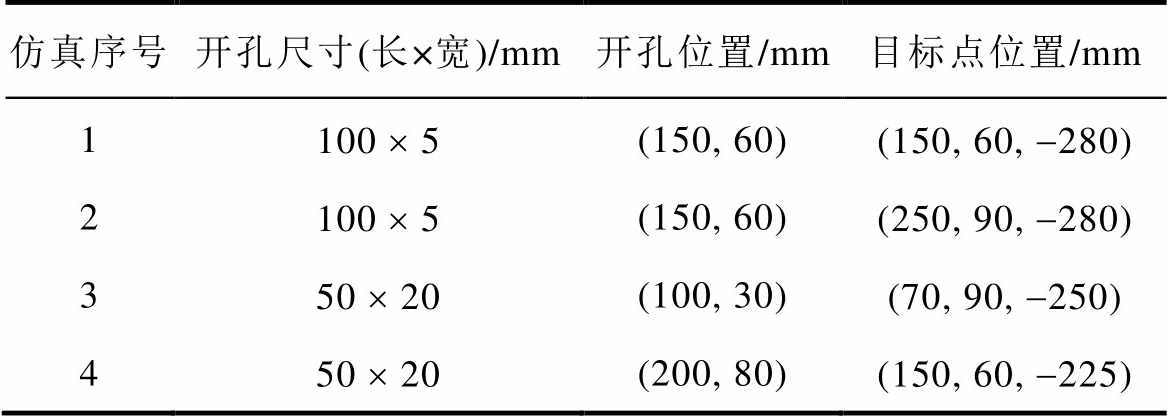
仿真序号开孔尺寸(长×宽)/mm开孔位置/mm目标点位置/mm 1100 ´ 5(150, 60)(150, 60, -280) 2100 ´ 5(150, 60)(250, 90, -280) 350 ´ 20(100, 30)(70, 90, -250) 450 ´ 20(200, 80)(150, 60,-225)
图7~图10为分别对应仿真1~仿真4,由本文解析模型和CST仿真得到的屏蔽效能对比。从图中可以看出,在所考虑频域范围内解析模型计算得到的结果与CST的仿真结果有较好的一致性;当频率大于腔体第二谐振频率时,解析模型的计算结果与CST的仿真结果吻合度降低,且随着频率的提高,两种方法得到的结果差距逐步增大,原因在于:①空气波导和有损介质波导的特性阻抗或导纳以及凸面结构的等效阻抗或导纳是基于TE10模式推导而来,但是不同的模式对应于不同的阻抗或导纳,BLT方法并没有像CST考虑了多模的影响;②对于仿真1和2,开孔尺寸长度100mm等于频率为1.5GHz的入射波波长的一半,发生孔缝谐振,BLT方法没有考虑这部分电磁损耗。因此相比于CST,利用本文算法计算得到的目标点电压偏高,从而屏蔽效能计算值偏低。
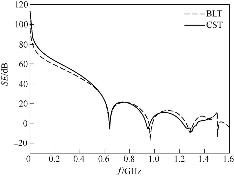
图7 仿真1对应的凸面结构腔体屏蔽效能对比
Fig.7 Comparison of the SE of the enclosure with convex structure for Case 1
图11为在仿真1的条件下,利用本文解析模型计算凸面结构腔体内有无介质板的屏蔽效能对比。从图11中可以看出,与空腔体相比,放置介质板之后,凸面腔体谐振得到有效抑制,谐振点附近的屏蔽效能得到显著提高,对远离谐振点频域的屏蔽效能影响较小。图12为在仿真1的条件下,频率固定在腔体第一谐振频率0.642GHz时屏蔽效能随介质板位置(pr的取值区间为[0, 70]mm)的变化曲线。从图12中可以看出,0.642GHz时,随着介质板右端到腔体末端的距离pr变大,屏蔽效能先减小后增大,在pr=16mm处取得极小值,在pr=70mm处取得极大值,因此可以根据具体要求合理安排介质板的位置,以达到理想的屏蔽效果。
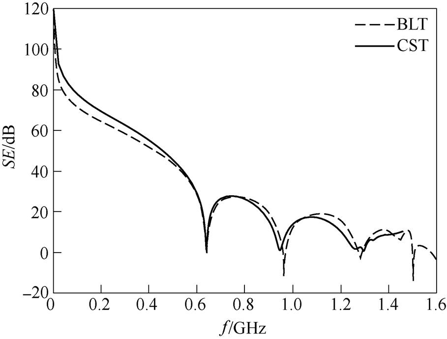
图8 仿真2对应的凸面结构腔体屏蔽效能对比
Fig.8 Comparison of the SE of the enclosure with convex structure for Case 2
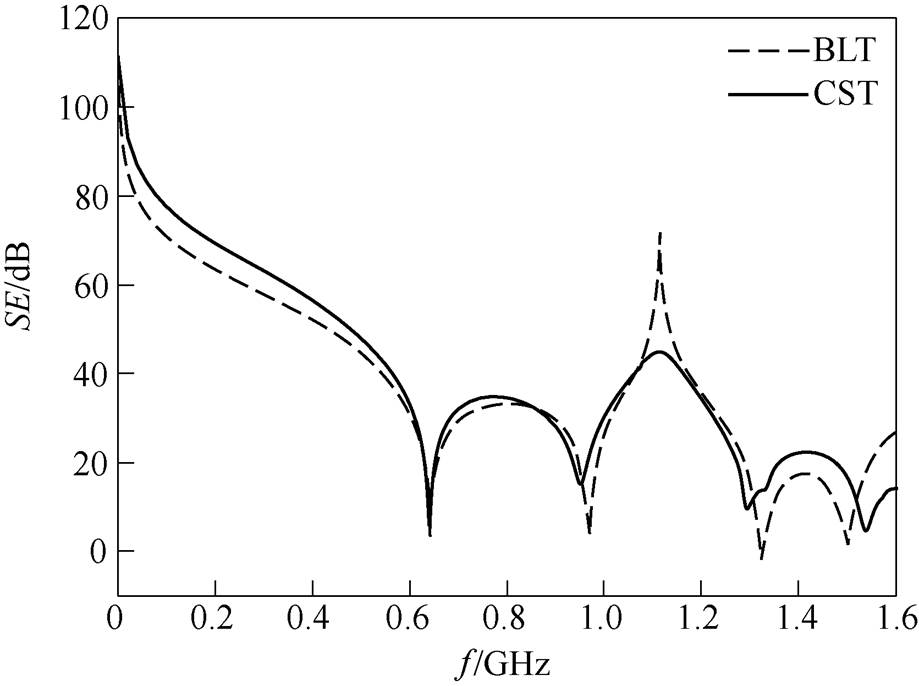
图9 仿真3对应的凸面结构腔体屏蔽效能对比
Fig.9 Comparison of the SE of the enclosure with convex structure for Case 3

图10 仿真4对应的凸面结构腔体屏蔽效能对比
Fig.10 Comparison of the SE of the enclosure with convex structure for Case 4

图11 有无介质板的凸面结构腔体屏蔽效能对比
Fig.11 Comparison of the SE with and without the dielectric layer
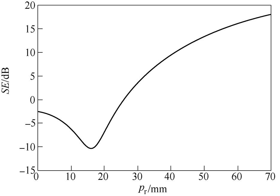
图12 f =0.642GHz时屏蔽效能随介质板位置的变化曲线
Fig.12 Variation of the SE with the position of the dielectric layer when f =0.642GHz
考虑图4中的阶梯结构腔体,假设左右两个腔体的尺寸分别为a´b1´d2=300mm´130mm´130mm和a´b2´(d-d2)=300mm´120mm´240mm,厚度为t =1mm,开孔尺寸为l´w=100mm´5mm,介质板参数与凸面结构腔体的一致,d01和d02的取值保持不变,仿真频率为0~1.6GHz。
设置3组仿真实验用于验证本文建立的解析模型的有效性,不同开孔位置和目标观测点(P1、P2)位置列于表2,其中仿真5为中心开孔且观测点位于开孔的中心轴线上,仿真6为中心开孔、观测点取任意位置,仿真7为偏心孔、观测点取任意位置。
图13~图15为分别对应仿真5~仿真7,由本文解析模型和CST仿真得到的观测点P1和P2的屏蔽效能对比。从图中可以看出,当频率小于腔体第二谐振频率时,利用解析模型计算得到的结果与CST的仿真结果吻合度比较高;当频率大于腔体第二谐振频率时,随着频率的提高,解析模型的计算结果与CST的仿真结果差距逐步增大,这与凸面结构腔体的情况类似。
表2 验证本文模型阶梯结构腔体的仿真参数
Tab.2 Simulation parameters for the verification of the model in this paper for the enclosure with stepped structure
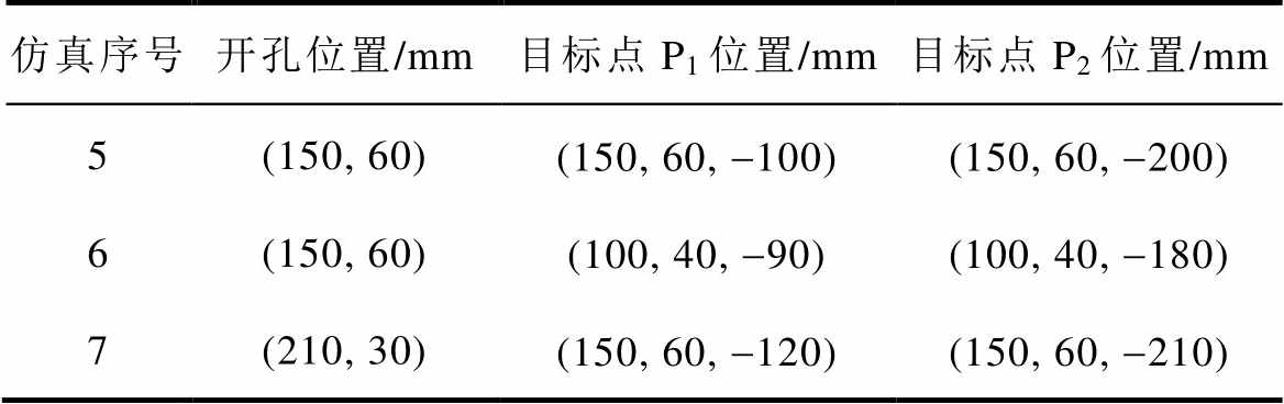
仿真序号开孔位置/mm目标点P1位置/mm目标点P2位置/mm 5(150, 60)(150, 60, -100)(150, 60, -200) 6(150, 60)(100, 40, -90)(100, 40, -180) 7(210, 30)(150, 60, -120)(150, 60, -210)
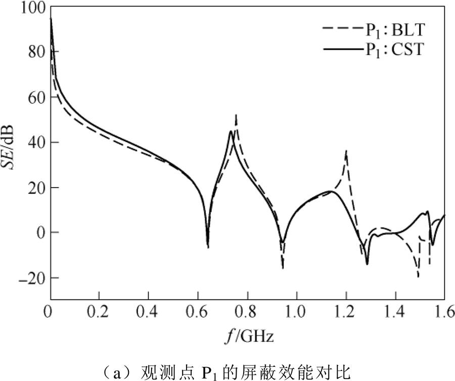

图13 仿真5对应的阶梯结构腔体屏蔽效能对比
Fig.13 Comparison of the SE of the enclosure with stepped structure for Case 5
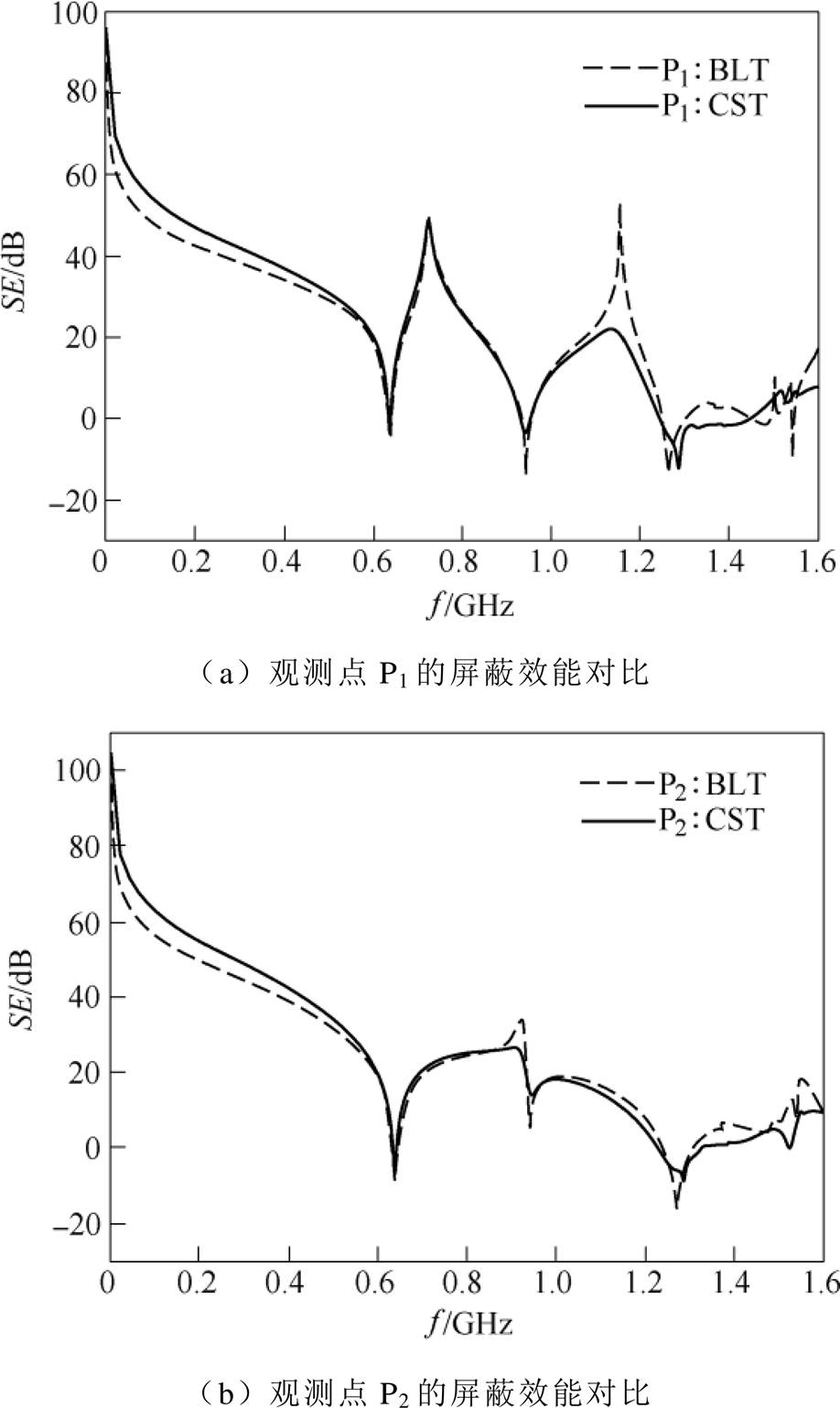
图14 仿真6对应的阶梯结构腔体屏蔽效能对比
Fig.14 Comparison of the SE of the enclosure with stepped structure for Case 6
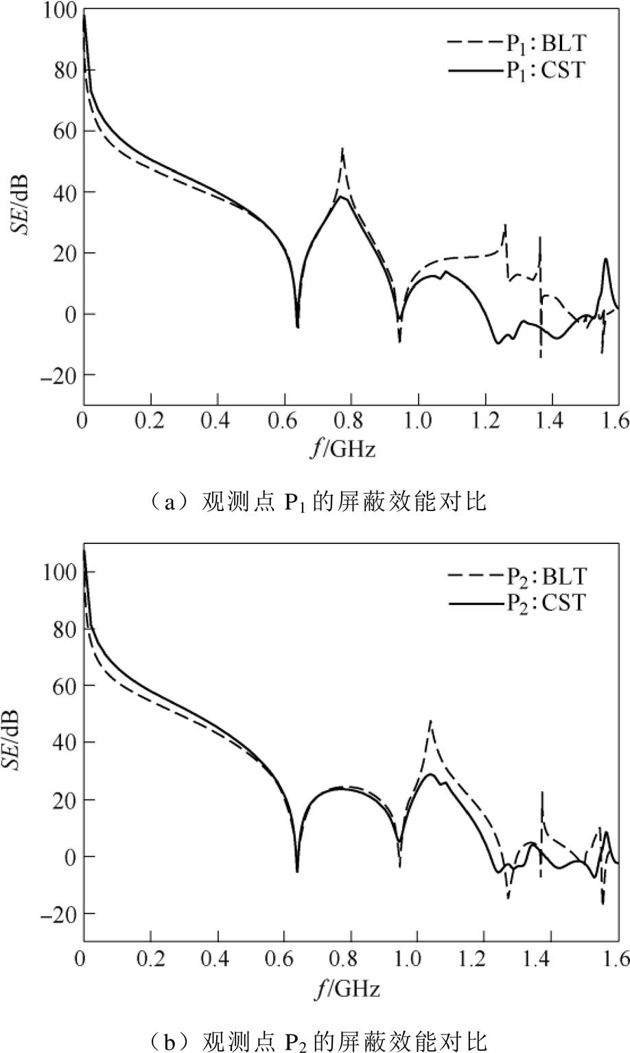
图15 仿真7对应的阶梯结构腔体屏蔽效能对比
Fig.15 Comparison of the SE of the enclosure with stepped structure for Case 7
上述算例均在同一计算机上完成,其配置为Intel(R) Xeon(R)E5-4607v2@2.6GHz处理器以及64GB内存。所有算例中BLT和CST所需的平均计算时间和内存见表3。可以看出,相比于全波软件CST,本文的计算方法节省了大量的计算时间,占用内存更少,证实了本文算法的高效性。
表3 所有算例中BLT和CST所需平均计算时间和内存
Tab.3 The average computational time and memory of BLT and CST of all cases
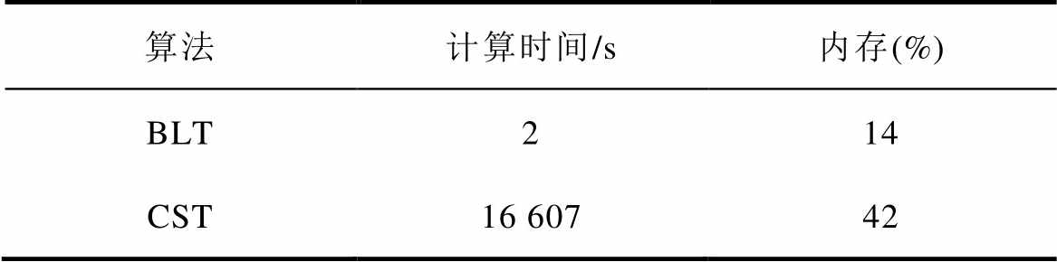
算法计算时间/s内存(%) BLT214 CST16 60742
本文针对内置介质板的异型开孔金属腔体的特点,基于电磁拓扑理论和BLT方程,分别建立了计算平面波照射下凸面结构腔体和阶梯结构腔体屏蔽效能的解析模型。通过与全波仿真软件CST的结果进行对比,验证了该解析模型的有效性和高效性,进而利用解析模型计算分析了介质板的位置等对异型腔体屏蔽效能的影响。计算结果表明:与空腔体相比,放置介质板可以有效抑制异型腔体的谐振情况,使得谐振点附近的屏蔽效能得到显著提高,但是对远离谐振点频域的屏蔽效能影响较小;不同谐振点处存在最佳介质板位置,使得谐振的抑制作用最强,在其取值区间内屏蔽效能最大。因此,在设计屏蔽腔体时,应该合理选择介质板的位置,以达到最佳的屏蔽效果。
与传统的BLT方法相比,本文的解析模型引入了开孔位置系数和观测点位置系数,因此可以处理任意位置开孔和任意位置观测点的情况;与全波分析方法相比,该解析模型计算效率更高,占用内存更少,而且便于分析介质板参数对异型腔体屏蔽效能的影响,为计算复杂结构腔体的屏蔽效能提供了一种简单有效的方法,对于电网的电磁屏蔽和防护具有指导意义。
参考文献
[1] 曹勇, 杨飞, 李春晖, 等. 不同耦合系数下的交错并联电流连续模式Boost功率因数校正变换器的传导电磁干扰[J]. 电工技术学报, 2019, 34(10): 2176- 2186.
Cao Yong, Yang Fei, Li Chunhui, et al. Conducted electromagnetic interference of interleaved continuous current mode Boost power factor correction converter with different coupling coefficients[J]. Transactions of China Electrotechnical Society, 2019, 34(10): 2176-2186.
[2] 江师齐, 刘艺涛, 银杉, 等. 基于噪声源阻抗提取的单相逆变器电磁干扰滤波器的设计[J]. 电工技术学报, 2019, 34(17): 3552-3562.
Jiang Shiqi, Liu Yitao, Yin Shan, et al. Electro- magnetic interference filter design of single-phase inverter based on the noise source impedance extraction[J]. Transactions of China Electrotechnical Society, 2019, 34(17): 3552-3562.
[3] 娄千层, 王世山, 高欣欣, 等. 基于部分移相网络级联的传输线远端串扰消除技术[J]. 电工技术学报, 2018, 33(17): 3965-3975.
Lou Qianceng, Wang Shishan, Gao Xinxin, et al. Far-end crosstalk cancellation of transmission lines based on partial phase shift network cascade[J]. Transactions of China Electrotechnical Society, 2018, 33(17): 3965-3975.
[4] 张露, 王永勤, 贺家慧, 等. 特高压变电站工频电磁场对避雷器在线监测装置测量准确度影响研究[J]. 电力系统保护与控制, 2018, 46(3): 164-169.
Zhang Lu, Wang Yongqin, He Jiahui, et al. Accuracy examination of linkage current online measurement of surge arresters under power frequency interference of electric field and magnetic field in the ultra-high voltage substations[J]. Power System Protection and Control, 2018, 46(3): 164-169.
[5] 冯利民, 王晓波, 吴联梓, 等. 500kV GIS变电站VFTO对于电子式互感器的电磁骚扰研究[J]. 电工技术学报, 2016, 31(1): 85-90.
Feng Limin, Wang Xiaobo, Wu Lianzi, et al. Study on the impact of VFTO electromagnetic interference on electronic transformers in 500kV GIS substation[J]. Transactions of China Electrotechnical Society, 2016, 31(1): 85-90.
[6] 秦红霞, 武芳瑛, 彭世宽, 等. 智能电网二次设备运维新技术研讨[J]. 电力系统保护与控制, 2015, 43(22): 35-40.
Qin Hongxia, Wu Fangying, Peng Shikuan, et al. New technology research on secondary equipment operation maintenance for smart grid[J]. Power System Protection and Control, 2015, 43(22): 35-40.
[7] 焦重庆, 牛帅, 李琳. 复合材料工频电场和工频磁场屏蔽效能实验研究[J]. 电工技术学报, 2015, 30(10): 1-6.
Jiao Chongqing, Niu Shuai, Li Lin. Experiment study of power frequency electric and magnetic shielding effectiveness for composite materials[J]. Transa- ctions of China Electrotechnical Society, 2015, 30(10): 1-6.
[8] Nie Baolin, Du Pingan. Electromagnetic shielding performance of highly resonant enclosures by a combination of the FETD and extended Prony’s method[J]. IEEE Transactions on Electromagnetic Compatibility, 2014, 56(2): 320-327.
[9] Solin J R. Formula for the field excited in a rectangular cavity with a small aperture[J]. IEEE Transactions on Electromagnetic Compatibility, 2011, 53(1): 82-90.
[10] 公延飞, 郝建红, 蒋璐行, 等. 基于Bethe小孔耦合理论和镜像原理的双腔体电磁泄漏的解析模型[J]. 电工技术学报, 2018, 33(9): 2139-2147.
Gong Yanfei, Hao Jianhong, Jiang Luhang, et al. An analytical model for electromagnetic leakage from double cascaded enclosures based on Bethe’s small aperture coupling theory and mirror procedure[J]. Transactions of China Electrotechnical Society, 2018, 33(9): 2139-2147.
[11] Robinson M P, Benton T M, Christopoulos C, et al. Analytical formulation for the shielding effectiveness of enclosures with apertures[J]. IEEE Transactions on Electromagnetic Compatibility, 1998, 40(3): 240- 248.
[12] Jongjoo S, Dong G K, Jong H K, et al. Circuital modeling and measurement of shielding effectiveness against oblique incidence plane wave on apertures in multiple sides of rectangular enclosure[J]. IEEE Transactions on Electromagnetic Compatibility, 2010, 52(3): 566-577.
[13] Yin Mingchu, Du Pingan. An improved circuit model for the prediction of the shielding effectiveness and resonance of an enclosure with apertures[J]. IEEE Transactions on Electromagnetic Compatibility, 2016, 58(2): 448-456.
[14] 范杰清, 郝建红, 柒培华. 基于扩展传输线法的异型腔电场屏蔽效能[J]. 电工技术学报, 2014, 29(5): 228-233.
Fan Jieqing, Hao Jianhong, Qi Peihua. Electric field shielding effectiveness of heterotypic enclosures based on adjusted transmission line method[J]. Transactions of China Electrotechnical Society, 2014, 29(5): 228-233.
[15] David W P, Thomas A C, Denton T K, et al. Model of the electromagnetic fields inside a cuboidal enclosure populated with conducting planes or printed circuit boards[J]. IEEE Transactions on Electromagnetic Compatibility, 2001, 43(2): 161-169.
[16] 路宏敏, 刘国强, 余志勇, 等. 加装印刷电路板的圆孔阵矩形机壳屏蔽效能[J]. 强激光与粒子束, 2009, 21(1): 108-112.
Lu Hongmin, Liu Guoqiang, Yu Zhiyong, et al. Shielding effectiveness of PCB loaded rectangular enclosure with circular-aperture array[J]. High Power Laser and Particle Beams, 2009, 21(1): 108-112.
[17] 杨楠. 双层加载电路板屏蔽腔屏蔽效能研究[J]. 现代电子技术, 2013, 36(22): 5-9.
Yang Nan. Study on shielding effectiveness of double-layer metallic enclosure with load print circuit[J]. Modern Electronics Technique, 2013, 36(22): 5-9.
[18] 张亚普, 达新宇, 谢铁城. 孔缝箱体屏蔽效能电磁拓扑分析模型[J]. 强激光与粒子束, 2014, 26(2): 228-233.
Zhang Yapu, Da Xinyu, Xie Tiecheng. Electro- magnetic topology model for shielding effectiveness estimation of metallic enclosure with apertures[J]. High Power Laser and Particle Beams, 2014, 26(2): 228-233.
[19] 张亚普, 达新宇, 谢铁城. 偏心孔缝箱体屏蔽效能电磁拓扑分析算法[J]. 电波科学学报, 2014, 29(5): 994-1002.
Zhang Yapu, Da Xinyu, Xie Tiecheng. Electro- magnetic topology algorithm of shielding effective- ness analysis of a metallic enclosure with off-center apertures[J]. Chinese Journal of Radio Science, 2014, 29(5): 994-1002.
[20] 罗静雯, 杜平安, 任丹, 等. 基于BLT方程的双层腔体屏蔽效能计算方法[J]. 强激光与粒子束, 2015, 27(11): 166-171.
Luo Jingwen, Du Pingan, Ren Dan, et al. BLT equation-based approach for calculating shielding effectiveness of double layer rectangular enclosure with apertures[J]. High Power Laser and Particle Beams, 2015, 27(11): 166-171.
[21] 胡溥宇, 赵昱, 杨锦鹏, 等. 任意平面波辐照下开孔矩形腔体屏蔽效能快速计算方法[J]. 电工技术学报, 2018, 33(15): 3651-3660.
Hu Puyu, Zhao Yu, Yang Jinpeng, et al. A fast approach for calculating the shielding effectiveness of enclosures with apertures under oblique plane wave illuminations[J]. Transactions of China Electro- technical Society, 2018, 33(15): 3651-3660.
[22] 阚勇, 闫丽萍, 赵翔, 等. 基于电磁拓扑的多腔体屏蔽效能快速算法[J]. 物理学报, 2016, 65(3): 0307021-03070212.
Kan Yong, Yan Liping, Zhao Xiang, et al. Electro- magnetic topology based fast algorithm for shielding effectiveness estimation of multiple enclosures with apertures[J]. Acta Physica Sinica, 2016, 65(3): 0307021-03070212.
[23] 郝建红, 蒋璐行, 范杰清, 等. 内置介质板的开孔箱体屏蔽效能电磁拓扑模型[J]. 电工技术学报, 2017, 32(9): 101-111.
Hao Jianhong, Jiang Luhang, Fan Jieqing, et al. Electromagnetic topology model for the shielding effectiveness of an apertured enclosure with a lossy dielectric layer[J]. Transactions of China Electro- technical Society, 2017, 32(9): 101-111.
[24] Marcuvitz N. Waveguide Handbook[M]. UK: IET, 1986.
The Shielding Effectiveness of Heterotypic Enclosures Embedded Dielectric Layers Based on the BLT Equation
Abstract The outer shape and inner structure will affect the shielding effectiveness (SE) of metallic enclosures. By deriving the scattering parameter of the equivalent circuit at the discontinuous position of the heterotypic enclosure, the analytical models for the SE of an enclosure with convex structure and an enclosure with stepped structure excited by a plane wave are established based on the electromagnetic topology theory and the BLT equation. The effects of the position of the dielectric layer on the SE of the heterotypic enclosure are then analyzed. The analytical model can be used to calculate the SE at any point in the enclosure with arbitrarily positioned aperture by introducing the coefficients of the aperture position and the observation point position. The results show that dielectric layer can effectively suppress the resonance of the heterotypic enclosure, which improves the SE for frequencies near the resonances while less affecting the SE for frequencies far away from the resonances. The optimal layer position exists at different resonance points, thus the SE reaches the maximum value within the interval of the layer position. The analytical results are in good agreement with those of the full-wave simulation software CST, which validates the efficiency of the analytical models. Compared with the numerical methods, the analytical model has higher efficiency and requires less memory, which has guiding significance for the shielding design of heterotypic enclosures.
keywords:Shielding effectiveness (SE), electromagnetic topology (EMT) theory, BLT equation, heterotypic enclosure, dielectric layer
中图分类号:TM15; TM25
DOI: 10.19595/j.cnki.1000-6753.tces.191050
国家自然科学基金(61372050)和中央高校基本科研业务费专项基金(2018QN013)资助项目。
收稿日期2019-08-16
改稿日期 2019-12-29
郝建红 女,1960年生,教授,博士生导师,研究方向为高功率微波、电磁场理论及混沌控制等。E-mail: jianhonghao@ncepu.edu.cn
蒋璐行 女,1991年生,博士研究生,研究方向为电工理论与新技术、电力系统电磁兼容。E-mail: 13261200137@163.com(通信作者)
(编辑 崔文静)