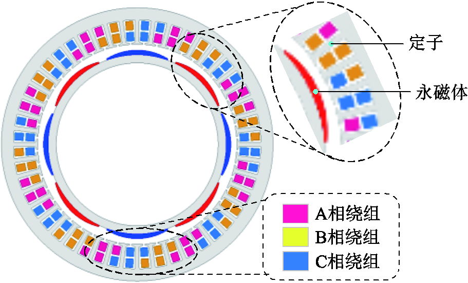
图1 8极48槽表贴式永磁同步电机横截面示意图
Fig.1 Cross section of 8-poles 48 slots surface-mounted permanent-magnet machine
摘要 采用极间虚齿结构对表贴式永磁电机的六倍频振动噪声进行削弱,与传统的优化方法相比,该方法结构简单,且基本不影响基波磁场和平均转矩。首先,基于麦克斯韦张量法,推导了考虑力波分量相角的六倍频电磁力谐波表达式,分析了六倍频电磁力的产生机理,并以一台8极48槽表贴式永磁电机为例,采用有限元法进行验证;接着,引入凸极磁导函数,基于磁场调制原理,分析了虚齿对磁通密度时间谐波的调制作用及对六倍频电磁力的削弱机理;然后,建立多物理场有限元模型,对比了优化前后电机的关键电磁性能以及振动和噪声频谱,结果表明,极间虚齿可有效削弱电机的六倍频电磁力和振动噪声;最后对优化后的样机进行噪声实验,与仿真结果对比,验证了理论和有限元模型的正确性。
关键词:极间虚齿 表贴式永磁同步电机 六倍频振动噪声 有限元法
永磁电机具有结构简单、功率密度高、效率高等优点,被广泛用于水下航行器推进系统[1-3]。然而,隐蔽性作为水下航行器的重要指标,容易受到永磁电机低频振动噪声的影响[4-5]。
在低频段,六倍频振动噪声是非常显著的,其由六倍频电磁力引起[6-10]。文献[6-8]分别分析了10极45槽、8极12槽、8极9槽、10极12槽四种分数槽永磁电机的电磁力和电磁振动特性,结果表明,六倍频振动是主要的峰值点。文献[9]对一台8极48槽永磁同步电机进行了噪声实验,结果表明,六倍频电磁力约为二倍频电磁力的三分之一,但其产生的噪声幅值却与二倍频噪声基本一致。文献[10]对一台8极48槽电动汽车用永磁电机的力波特性进行分析,结果表明,六倍频电磁力是零阶力波的主要频率分量;通常来讲,模态越低,振动越强,较小的低阶力波即可引起较大的振动噪声[11]。六倍频电磁力与3次、5次和7次磁通密度谐波密切相关,由于这些磁场谐波在永磁电机中占比较大,这导致六倍频电磁力及其振动噪声普遍都显著地存在于各类永磁电机中[12]。因此,针对六倍频电磁力的分析和削弱是十分必要的。
目前,国内外已有许多学者对电机振动噪声的削弱方法进行研究[13-18]。文献[13]以一台6极36槽永磁电机为例,提出了一种极间填充永磁体的方法来削弱振动,该方法对二倍频振动噪声的削弱非常有效,但是对六倍频振动噪声的削弱并不明显。文献[14]以一台8极48槽永磁电机为例,基于麦克斯韦张量法,分析了转子分段斜极对电机径向力波谐波的影响,结果表明,当转子被分为5段且斜极角度为3°时,六倍频电磁力可以被有效降低,但是平均转矩下降了5%。文献[15]提出了一种定子齿顶偏移的结构来削弱一台6极36槽内置式永磁电机的振动,但是平均转矩下降了4%。此外,还有定子齿削角[16],斜槽[17]及转子表面插入铜环[18]等方法,可用来削弱六倍频振动噪声,但是这些方法都有一个共性问题,即影响基波磁场,导致平均转矩严重下降。而且,目前基于转子侧的优化方法普遍比较复杂,会导致电机成本的增加和转子可靠性的降低[9,13,18]。因此,如何在保证平均转矩基本不变的情况下,提出一种简单可靠的方法,有效削弱六倍频振动噪声是一个亟待解决的问题。
本文采用极间虚齿结构对表贴式永磁电机的六倍频振动噪声进行削弱,并基于磁场调制机理[19-20],解释了虚齿对六倍频电磁力谐波及基波磁场的影响。首先,基于麦克斯韦张量法,分析了六倍频电磁力的产生机理;接着,引入凸极磁导函数,结合有限元模型分析了虚齿对气隙磁场时间谐波及六倍频电磁力的影响。然后,建立多物理场耦合模型,对比了优化前后电机的电磁性能及振动噪声频谱;最后,将优化后样机的仿真结果与噪声实验结果进行对比,验证了理论及有限元模型的正确性。考虑到空载状态的噪声响应即可反映该电机的噪声趋势与特征[21],因此,为方便起见,本文主要对样机空载下的六倍频电磁力谐波进行分析,并使用有限元法验证了虚齿结构在负载工况的有效性,所得结论可以为表贴式永磁电机六倍频振动噪声的削弱提供有价值的参考。
本文以一台8极48槽表贴式永磁电机为例进行分析,其横截面示意图如图1所示。电机的基本参数见表1,定子采用斜槽结构,用来削弱槽频振动[17]。
图1 8极48槽表贴式永磁同步电机横截面示意图
Fig.1 Cross section of 8-poles 48 slots surface-mounted permanent-magnet machine
表1 样机基本参数
Tab.1 The basic parameters of prototype
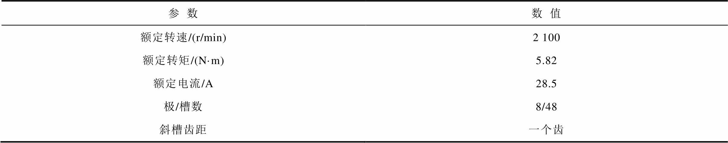
参数数值 额定转速/(r/min)额定转矩/(N·m)2 1005.82 额定电流/A28.5 极/槽数斜槽齿距8/48一个齿
样机定、转子简化示意图如图2所示。其中,θ是转子位置角,当θ=0°时,永磁体中心线与定子某个齿的中心线对齐。α是转子相对于参考位置的旋转角度。
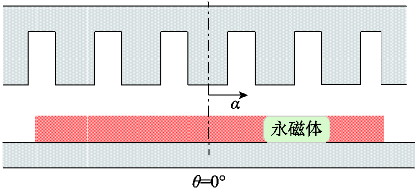
图2 样机定、转子简化模型
Fig.2 The simplified model of the stator and rotor
六倍频振动噪声主要由六倍频电磁力谐波引起,分析六倍频电磁力谐波的形成原因是降低六倍频振动噪声的关键。本文基于麦克斯韦张量法与磁场调制机理,分析六倍频电磁力谐波与磁场谐波的关系,从而得到六倍频电磁力谐波的产生机理。
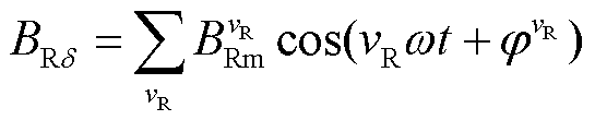
定子齿表面相当于等势面,其中心位置基本不受开槽效应影响,则在永磁磁场作用下,定子齿表面中心线上一点的磁通密度随时间的变化曲线为[22-24]
 (1)
(1)
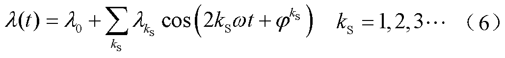
式中,ω为定子基波电流角频率;t为时间; 和
和 分别为vR次时间谐波的幅值和相位;vR=2kR-1,kR=1, 2, 3,
 。
。
需要强调的是,本文旨在分析六倍频电磁力时间谐波,其与磁通密度时间谐波直接相关,因此,在磁场分析时,不再考虑磁场的空间分布特性,而主要考虑定子齿表面中心线上一点随时间(或者随转子转过的电角度)的变化。在分析过程中,基波代表频率为基频的谐波,即1次时间谐波。
根据麦克斯韦张量法[25-27],且忽略幅值较小的切向磁通密度,定子齿表面单位面积上受到的径向电磁力为[28]
 (2)
(2)
式中, 为真空磁导率。
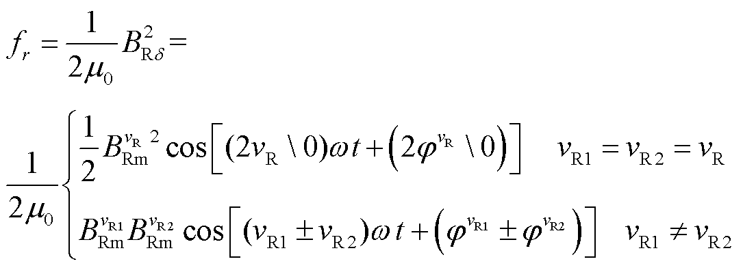
由式(2)可以看出,对于特定的电磁力谐波,其由多个力波分量组成,这些力波分量之间磁通密度谐波含量不同,相互作用关系受到各个分量相位的影响。为方便起见,定义F(vR1, vR2)为由vR1和vR2次磁通密度时间谐波组成的力波分量。
组成六倍频电磁力谐波的分量需要
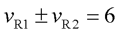 (3)
(3)
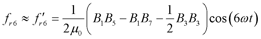
忽略幅值较小的磁通密度高次谐波,主要考虑1、3、5、7次等幅值较大的磁场谐波之间的相互作用,则六倍频电磁力主要由F(1, 5)、F(1, 7)、F(3, 3)组成,因此,六倍频电磁力谐波可表示为
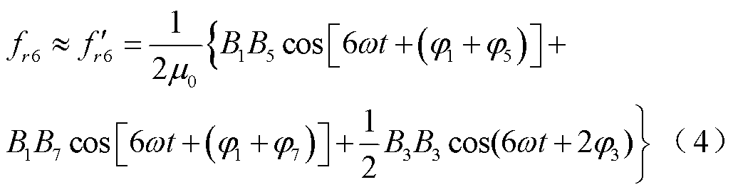
式中,B1、B3、B5和B7分别为1次、3次、5次和7次磁通密度时间谐波幅值; 为由F(1, 5)、F(1, 7)、F(3, 3)相互作用形成的六倍频电磁力谐波,其相互作用关系由各自的相位决定。
结合样机有限元模型,计算得到磁通密度时间谐波波形及其快速傅里叶变换(Fast Fourier Transform, FFT)分解结果如图3所示。在图3b中,通过幅值的正负来区分各次谐波的初始相位;当幅值为正时,相位为0;幅值为负时,相位为π。
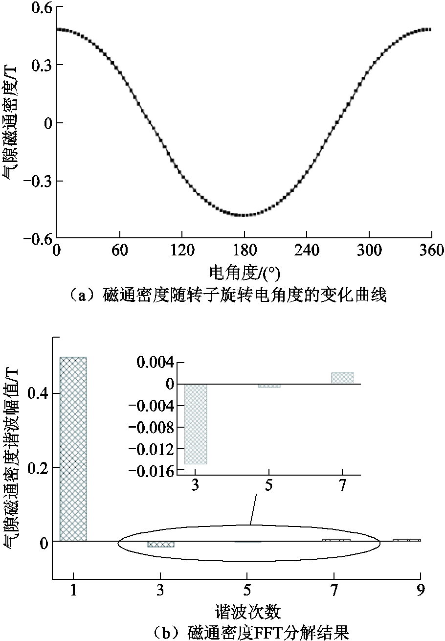
图3 磁通密度曲线及其FFT分解结果
Fig.3 The curve and FFT results of the flux density
基于有限元计算结果与式(4),可以确定F(1, 7)和F(3, 3)为正向分量,F(1, 5)为负向分量,即式(4)可简化为
 (5)
(5)
 及其各个力波分量的波形及幅值关系如图4所示,可以发现,由于F(1, 7)和F(3, 3)幅值之和的绝对值大于F(1, 5)幅值的绝对值,导致正负分量之间无法相互抵消,从而引起了六倍频电磁力。因此,可通过正负力波分量之间的相互补偿关系来削弱六倍频电磁力。从磁通密度时间谐波来看,即尽量减小5次谐波与7次谐波的差值,以及减小3次谐波的幅值。
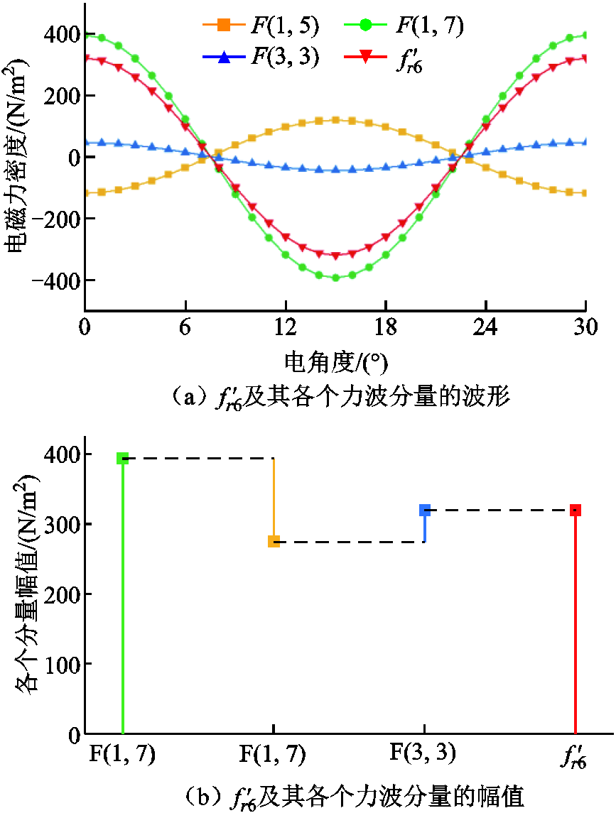
图4  及其各个力波分量的关系
Fig.4 The relationship of and each force component
与 的对比如图5所示,两者幅值对比见表2,误差为3%,基本可以忽略。因此,可以替代,两者的对比验证了六倍频电磁力谐波产生机理的正确性。
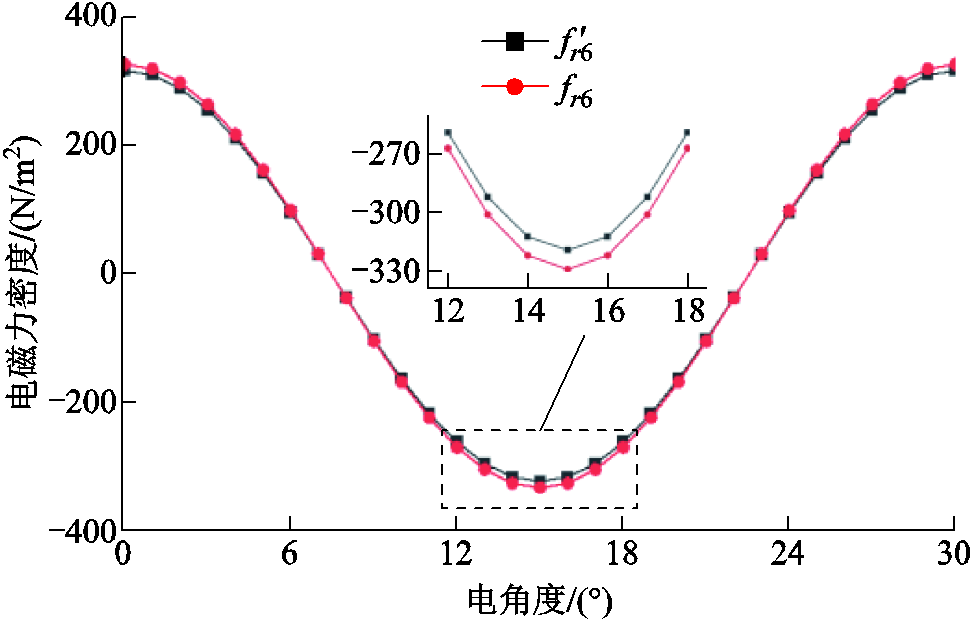
图5 与 的对比
的对比
Fig.5 The comparison of and
表2 与的幅值对比
Tab.2 The comparison of amplitudes of and

参数/(N/m2)/(N/m2)误差(%) 最大值和误差3203303
加入极间虚齿后转子横截面示意图如图6所示,两个相邻磁极之间增加铁心凸起结构。该凸起结构类似于定子齿,会导致转子铁心具有齿槽效应,但齿间无绕组,因此称之为极间虚齿。在圆周方向,虚齿与面嵌式永磁电机的极间凸起一致,位于相邻的永磁体之间,其周向宽度恰好与永磁体互补,可用于永磁体定位。增加虚齿结构的转子等效简易模型如图7所示。在图7中,h为极间虚齿的径向厚度。本节中,计算结果均以h=1.2mm的模型为基础。

图6 加入极间虚齿后转子横截面示意图
Fig.6 Cross section of rotorwith interpolar virtual teeth
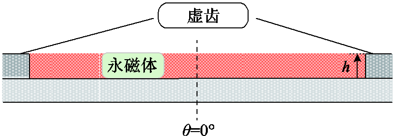
图7 加入极间虚齿后转子等效模型
Fig.7 Equivalent model of rotorwith interpolar virtual teeth
极间虚齿相当于转子辅助齿,会引起气隙磁导发生改变。根据已经取得的研究成果[29],可引入凸极磁导函数来表征虚齿引入的谐波磁导,即
式中, 为平均磁导;
 和
和 分别为谐波磁导的幅值和相位。
永磁体作用下,定子齿表面中心线一点的磁动势随时间变化的表达式为[30-31]
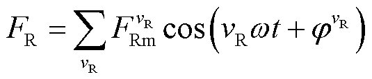 (7)
(7)
式中, 和分别为vR次谐波磁动势的幅值和相位。
将式(7)永磁磁动势作用于式(6)凸极磁导函数,可得到该点在虚齿影响下的磁通密度为
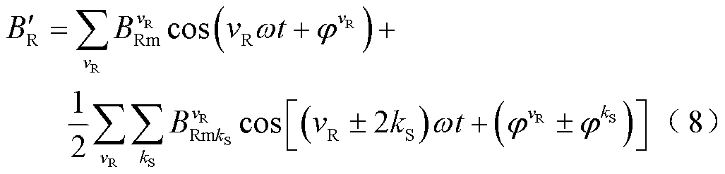
式中, 为谐波磁导影响下的磁通密度时间谐波幅值,
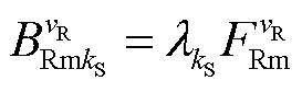 。
。
对比式(1)与式(8),可以发现,引入虚齿后,磁通密度谐波的频率成分并没有变化,但是谐波磁导会对原有磁场谐波形成调制作用,改变与其相差2kS次谐波磁通密度的幅值。调制效应与谐波磁导的相位相关,调制程度正比于谐波磁导幅值和相应磁通密度谐波幅值的乘积。
定子齿表面中心上一点的磁导随时间的变化可表示为
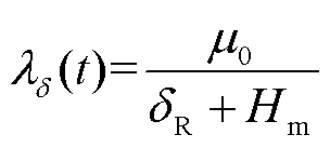 (9)
(9)
式中, 为等效气隙长度;
 为永磁体厚度。
一个电周期内该点磁导随时间的变化曲线及其FFT结果如图8所示。图8中,当幅值为正时,相位为0;幅值为负时,相位为π。
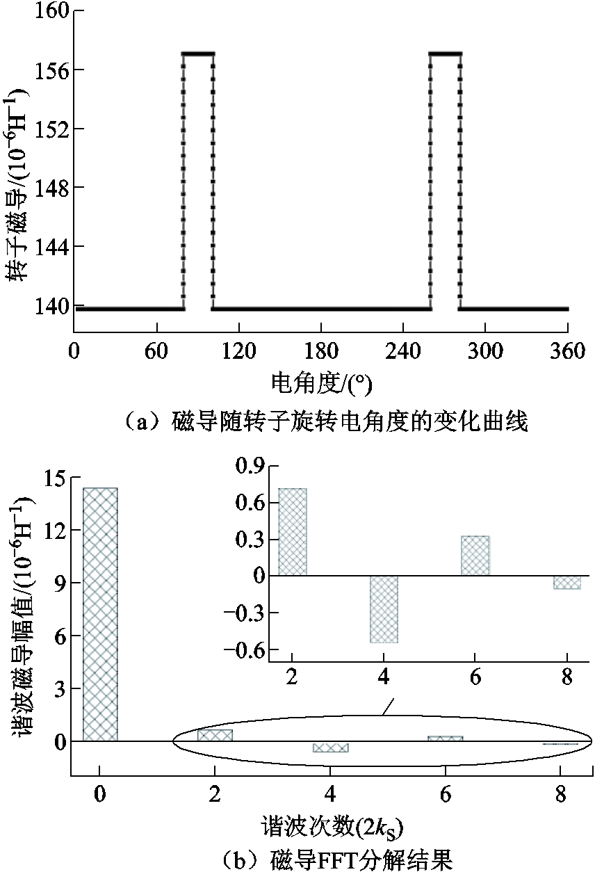
图8 磁导波形及其FFT分解结果
Fig.8 The curve and FFT results of the permeance
基于式(8)及有限元计算结果,以3次谐波为例,进一步讨论虚齿对磁场谐波的调制效应。由于其他谐波磁通密度幅值较小,仅考虑基波在凸极磁导调制后对3次谐波的影响,且忽略谐波之间相互作用关系的迭代效应。基波磁场可分别与2次磁导与4次磁导相互作用,调制得到3次谐波磁场,由式(8)可以确定,基波与2次磁导相互作用后,得到的3次谐波磁场为负向分量;基波与4次磁导相互作用后得到的3次谐波磁场为正向分量。则调制后,3次谐波幅值变化量为
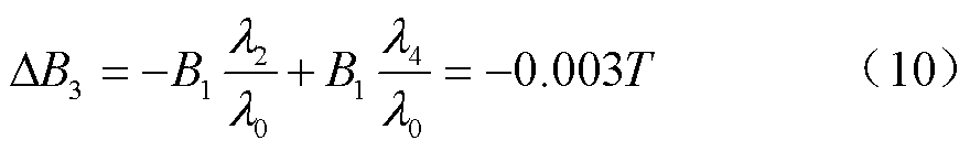
同理,可以得到调制后基波及其他谐波的幅值变化量见表3。表3中,基波的变化量主要由3次谐波与2次和4次磁导分别作用,5次谐波与4次和6次磁导分别作用,7次谐波与6次磁导分别作用得到,由于其变化量较小,结果仅给出了变化量总和。
表3 基波及其他谐波的变化量
Tab.3 The changes of the fundamental wave and other main harmonics
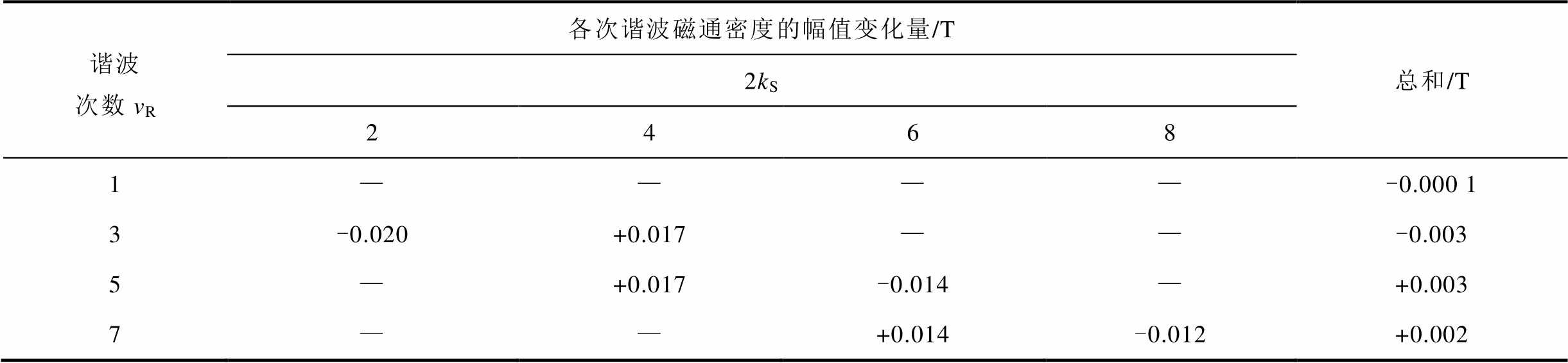
谐波次数vR各次谐波磁通密度的幅值变化量/T总和/T 2kS 2468 1————-0.000 1 3-0.020+0.017——-0.003 5—+0.017-0.014—+0.003 7——+0.014-0.012+0.002
分析表3可知:
1)由于基波磁场的幅值变化量主要由幅值较小的谐波磁场与相应磁导相互作用得到,变化量较小,基本可以忽略,因此,虚齿基本不影响基波磁场。
2)由于2次谐波磁导幅值大于4次谐波磁导幅值,因此,虚齿对3次谐波磁场表现为削弱作用。
3)虚齿对5次和7次谐波磁场表现为增大作用,而5次谐波磁场增加量大于7次谐波磁场增加量,因此,虚齿的引入减小了5次和7次谐波磁场的差值。
因此,虚齿主要依靠调制作用,降低3次谐波,并减小5次和7次谐波磁场的差值来削弱六倍频电磁力谐波,且基本不影响基波磁场。
加入虚齿后,气隙磁通密度随时间的变化曲线及其FFT分解结果如图9所示。图9中,e为5次谐波和7次谐波差值。各次谐波的变化量与3.1节中计算结果存在差异,但变化趋势相同。误差主要由未考虑除基波外其他谐波之间的相互作用以及调制关系的迭代效应引起,并不影响各次谐波的变化趋势。图9b中,3次谐波的降低以及5次谐波和7次谐波差值e的减小,与3.1节中所得结论基本一致,验证了3.1节中理论分析的正确性。
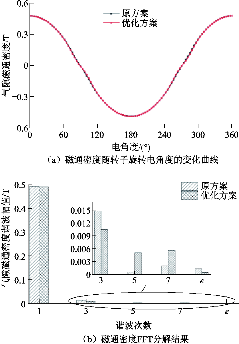
图9 原方案与优化方案磁通密度对比
Fig.9 The comparison of the flux density between the original scheme and the optimized scheme
虚齿的高度会影响其调制特性,六倍频电磁力谐波幅值随虚齿高度h的变化趋势如图10所示。
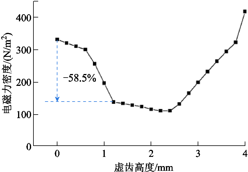
图10 六倍频电磁力谐波幅值随虚齿高度变化曲线
Fig.10 The curve of amplitude of the sixth harmonic with the height of the virtual tooth
考虑到电机结构,虚齿高度被限定在0~4mm,即不超过永磁体的厚度。可以发现,随着高度的增加,六倍频电磁力先减小后增大。
1)在0~0.6mm范围内,六倍频电磁力幅值缓慢下降。
2)在0.6~1.2mm范围内,随着虚齿高度增加,六倍频电磁力幅值快速下降。
3)在1.2~2.4mm范围内,六倍频电磁力幅值趋于平缓,六倍频电磁力幅值变化不明显;h=1.2mm恰好为下降速度的转折点。
4)在2.4~4mm范围内,六倍频电磁力幅值逐渐增大。
由于h=1.2mm恰好为下降速度的转折点,h继续增加虚齿高度至2.4mm的过程中,六倍频电磁力变化并不明显,因此本文选用h=1.2mm作为优化方案,与原方案相比,六倍频电磁力谐波降低了58.5%。
优化前后空载下电机的电磁力密度随时间变化曲线及其FFT分解结果如图11所示。可以看出,除六倍频电磁力以外,与优化前相比,电机的2倍频和4倍频电磁力密度幅值基本不变,8倍频、10倍频及12倍频电磁力谐波略有增大,但是考虑到这三种谐波占比较小,且并非主要的激振源,因此其变化程度基本可以忽略。
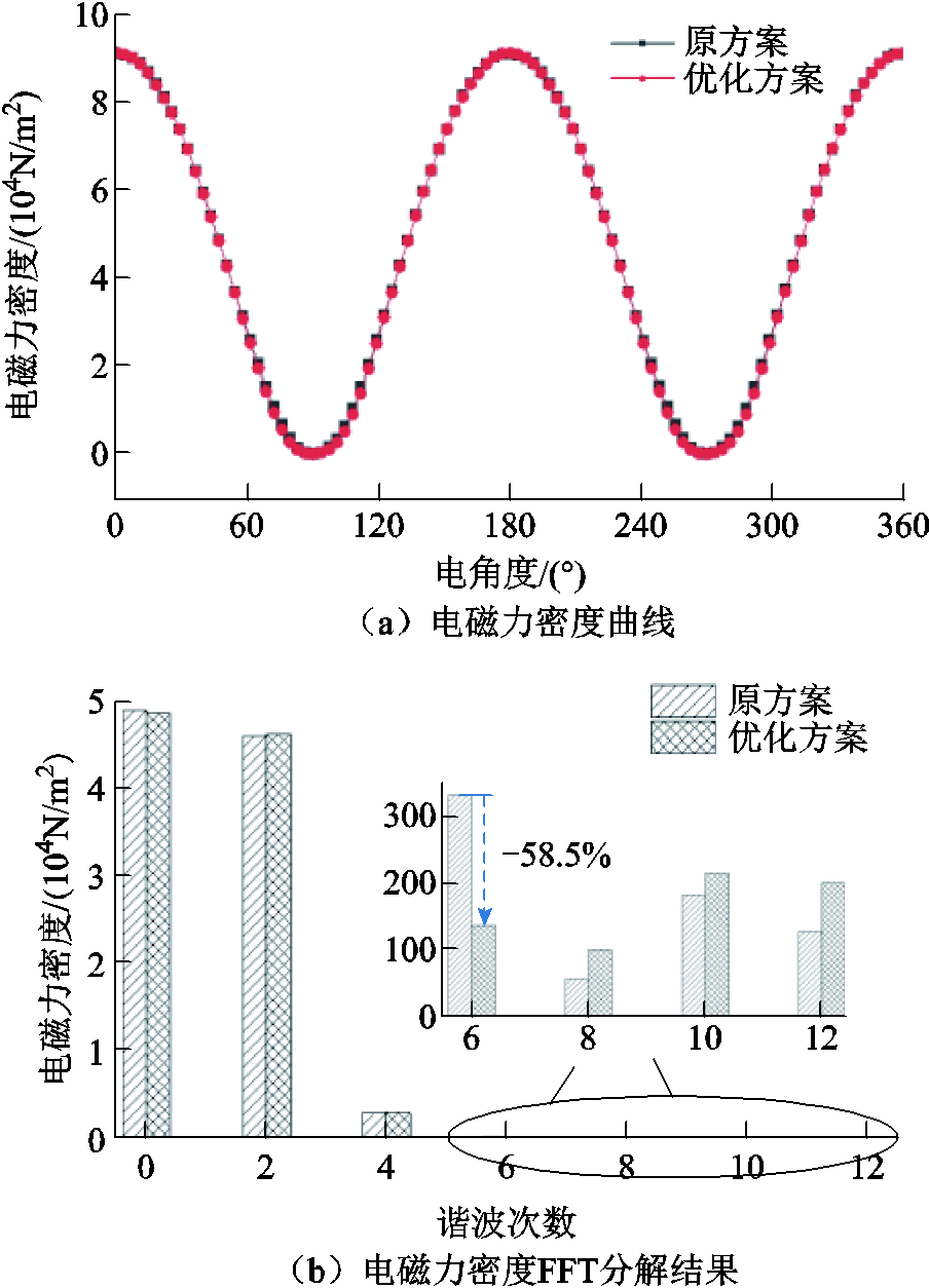
图11 空载下原方案与优化方案电磁力密度对比
Fig.11 The comparison of the electromagnetic force density between the original scheme and the optimized scheme under no load
优化前后电机的齿槽转矩随时间变化曲线及其FFT分解结果如图12所示。可以看出,优化后样机的齿槽转矩峰峰值有所增大,但是相对于额定转矩(5.82N·m)来说,其仅占比0.4%,因此基本可以忽略。
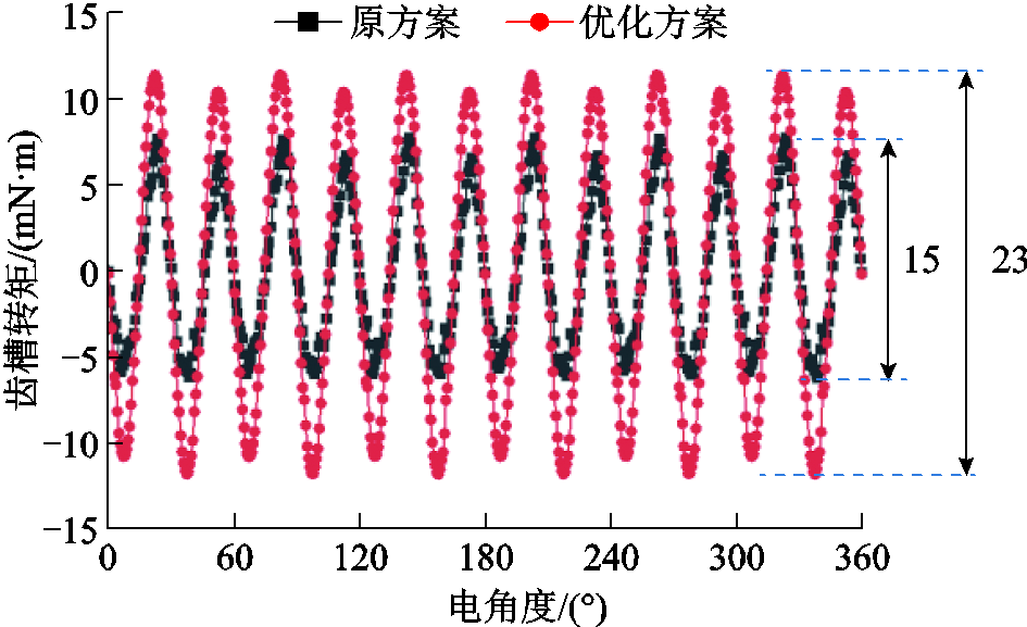
图12 原方案与优化方案齿槽转矩对比
Fig.12 The comparison of the cogging torque between the original scheme and the optimized scheme
优化前后负载下电机的电磁力密度随时间变化曲线及其FFT分解结果如图13所示。可以看出,六倍频电磁力谐波幅值明显下降,因此,极间虚齿结构在空载极负载工况下均可有效削弱六倍频电磁力谐波。
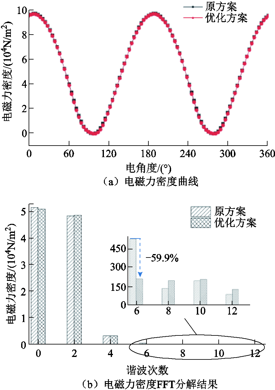
图13 负载下原方案与优化方案电磁力密度对比
Fig.13 The comparison of the electromagnetic force density between the original scheme and the optimized scheme under load
额定电流下,优化前后,电机的平均转矩曲线如图14所示,三种情况的平均转矩见表4。可以看出,当采用Id=0方式时,优化后样机的平均转矩降低了0.19%,当采用最大转矩电流比方式时,优化后样机的平均转矩降低了0.15%,下降幅度小于Id=0控制方式;两种控制方式下,平均转矩的下降基本可以忽略。因此,虚齿基本不影响平均转矩。
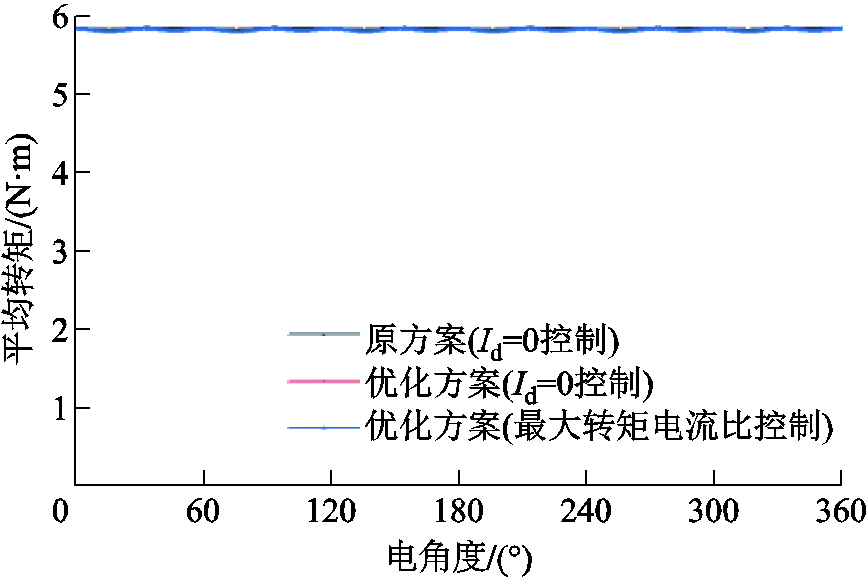
图14 原方案与优化方案平均转矩对比
Fig.14 The comparison of the average torque of the original scheme and the optimized scheme
表4 原方案与优化方案平均转矩对比
Tab.4 The comparison of the average torque of the original scheme and the optimized scheme

参数原方案(Id=0)优化方案(Id=0)优化方案(最大转矩电流比) 平均转矩/(N·m)5.8205.8095.811 与原方案相比变化程度(%)—-0.19-0.15
为了验证该方法的通用性,本文增加了虚齿结构对不同极槽配合永磁电机六倍频电磁力谐波的影响分析。8极9槽、8极18槽及10极12槽三种极槽配合永磁电机的有限元模型如图15所示。
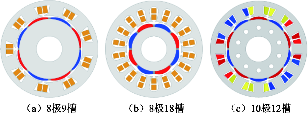
图15 不同极槽配合永磁电机有限元模型
Fig.15 The FEM of the PMSMs with different pole slot combinations
添加虚齿结构前后,三种极槽配合电机六倍频电磁力谐波计算结果如图16所示。可以看出,添加虚齿后,三种极槽配合电机六倍频电磁力谐波幅值均明显降低,其中,8极18槽方案六倍频电磁力谐波下降最明显,8极9槽方案六倍频电磁力谐波下降幅度最小。综合虚齿结构在不同极槽配合电机的应用效果,该方法对六倍频电磁力谐波的削弱具有较好的通用性。
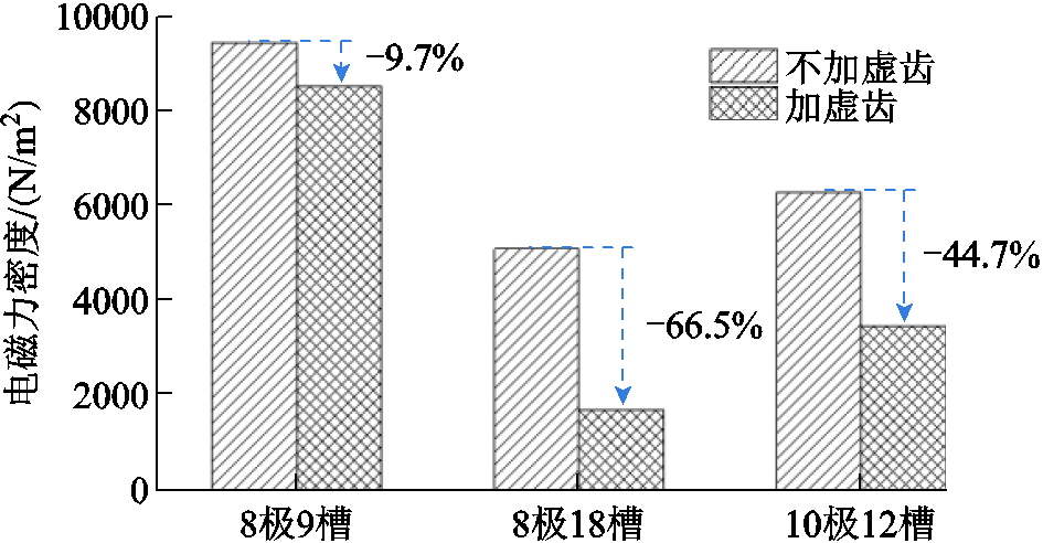
图16 不同极槽配合下虚齿对六倍频电磁力谐波的影响
Fig.16 The effects of the virtual teeth structure on six times frequency radial force harmonic under different combinations of pole and slot
样机定子结构及其3D有限元模型如图17所示,主要包含定子、机壳、端盖。
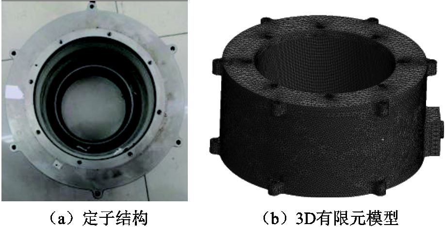
图17 样机定子模型
Fig.17 The stator model of the prototype
当电机特定阶次电磁力频率接近定子相应模态固有模态频率时,电机会发生共振现象[10]。优化结构位于转子,不影响定子结构件模态。定子各阶模态振型及其固有频率如图18所示。为清晰起见,在展示定子模态振型时,隐藏其他结构件。由图18可知,额定工况下,计算得到的电机固有频率与电磁力频率相差较远,因此,电机不会发生共振。
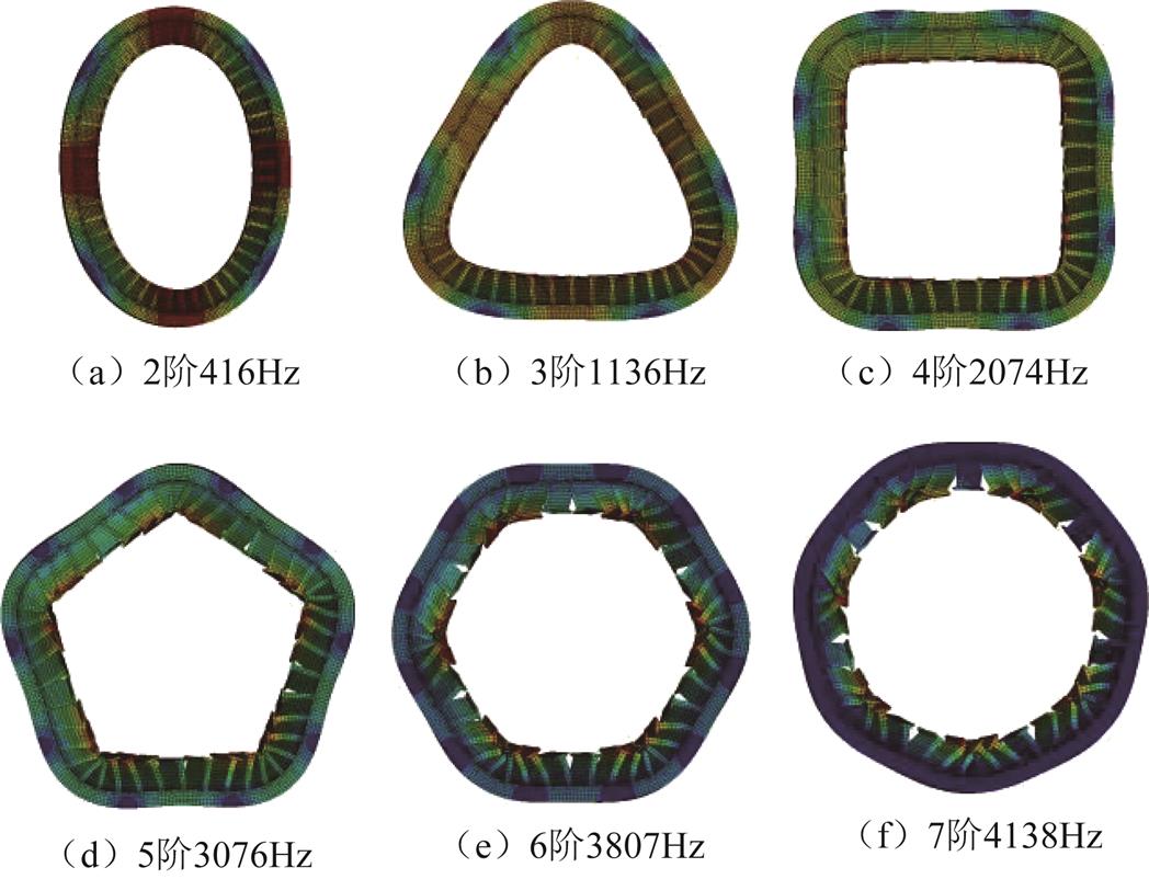
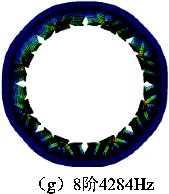
图18 样机定子模态振型图
Fig.18 The modal shape diagram of the stator
优化前后样机的振动频谱如图19所示。可以看出,主要的频率点包括6f、12f、18f等6f及其倍数点,其中6f处振动加速度幅值最大。与原方案相比,6f处振动加速度幅值由0.856m/s2下降至0.475 m/s2,降低44.5%。12f处振动加速度幅值略微增加,但与6f处幅值相比,仍然较小,因此其变化基本可以忽略。
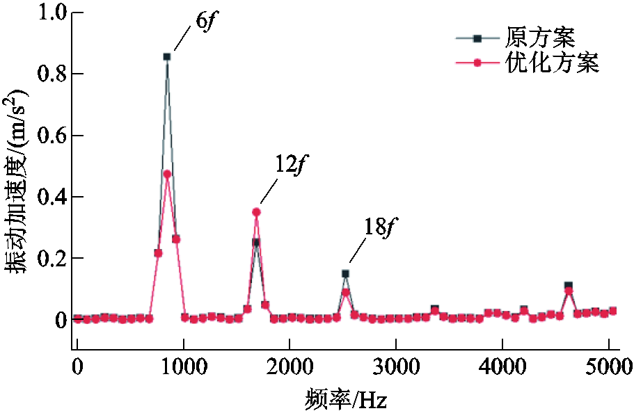
图19 样机振动加速度频谱对比
Fig.19 The comparison of vibration acceleration spectrum of the prototype
优化前后样机的声压级(Sound Pressure Level, SPL)如图20所示。与振动加速度频谱相比,趋势基本一致,主要频率点仍为6f及其倍数点。与原方案相比,6f处噪声幅值明显下降,证明了本文优化方法的有效性。
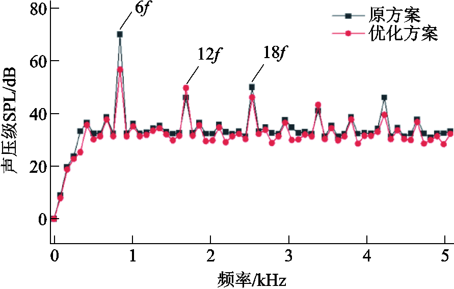
图20 样机SPL频谱对比
Fig.20 The comparison of SPL spectrum of the prototype
为了验证分析理论及方法的正确性,本文对优化后样机进行噪声实验。噪声实验设置如图21所示。电机被放在消声室内,传感器置于离电机机壳表面1m位置。麦克风及数据采集器均为丹麦BK公司生产。

图21 样机噪声测试实验图
Fig.21 The noise test experiment of the prototype
额定转速下,噪声实验结果如图22所示。可以看出,仿真结果存在一定误差,这主要是因为进行有限元仿真时,对模型进行了适当的简化和等效,且未考虑机械结构及固定方式等因素的影响。但误差在可接受的范围内,两者趋势基本一致,主要峰值频率点均为6f、12f、18f等6f及其倍数点。因此,有限元结果与实验结果的对比,可验证理论分析及仿真结果的有效性。
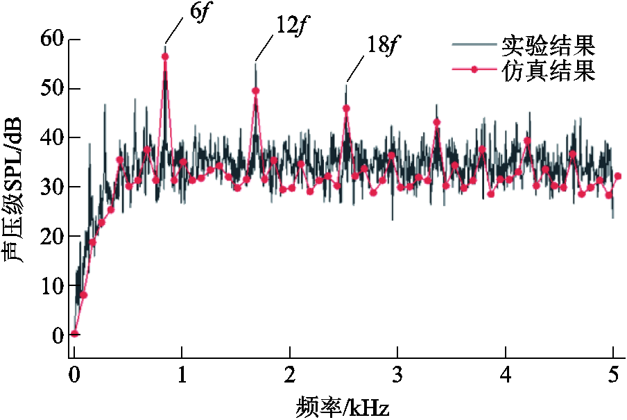
图22 SPL频谱仿真与实测对比
Fig.22 The comparison of SPL spectrum simulation and measurement
本文采用极间虚齿的结构对表贴式永磁电机六倍频振动噪声进行削弱。首先,基于麦克斯韦张量法与磁场调制原理,解释了虚齿削弱六倍频电磁力的机理;接着,分析了极间虚齿结构在不同工况及电机拓扑结构的有效性;最后,对优化后样机进行了噪声实验, 验证了仿真及理论的正确性。所得结论可以为表贴式永磁电机六倍频振动噪声的削弱提供有价值的参考。
1)六倍频电磁力主要由F(1, 5),F(1, 7),F(3, 3)相互作用得到,其中正向分量与负向分量的差值决定了六倍频电磁力的大小。
2)虚齿会引起凸极效应,对原有气隙磁场形成调制作用。以本文8极48槽样机为例,适当高度的虚齿可以降低3次谐波的幅值,减小5次与7次谐波之间的差值,从而有效地削弱六倍频电磁力及其引起的振动噪声。此外,虚齿基本不影响基波磁场及平均转矩,可以有效保证电机转矩密度不变。
参考文献
[1] Liu Guangwei, Qiu Guohua, Shi Jin, et al. Study on counter-rotating dual-rotor permanent magnet motor for underwater vehicle propulsion[J]. IEEE Transactions on Applied Superconductivity, 2018, 28(3): 1-5.
[2] Chasiotis I D, Karnavas Y L. A generic multi-criteria design approach toward high power density and fault-tolerant low-speed PMSM for pod applications[J]. IEEE Transactions on Transportation Electrification, 2019, 5(2): 356-370.
[3] Li Wei, Cheng Ming. Investigation of influence of winding structure on reliability of permanent magnet machines[J]. CES Transactions on Electrical Machines and Systems, 2020, 4(2): 87-95.
[4] Chai Feng, Li Yi, Pei Yulong, et al. Analysis of radial vibration caused by magnetic force and torque pulsation in interior permanent magnet synchronous motors considering air-gap deformations[J]. IEEE Transactions on Industrial Electronics, 2019, 66(9): 6703-6714.
[5] Xu Jiaqun, Zhang Hongqiang. Random asymmetric carrier PWM method for PMSM vibration reduction[J]. IEEE Access, 2020, 8: 109411-109420.
[6] 陈益广, 韩柏然, 沈勇环, 等. 永磁同步推进电机电磁振动分析[J]. 电工技术学报, 2017, 32(23): 16-22. Chen Yiguang, Han Boran, Shen Yonghuan, et al. Electromagnetic vibration analysis of permanent magnet synchronous propulsion motor[J]. Transactions of China Electrotechnical Society, 2017, 32(23): 16-22.
[7] Sun Tao, Kim Y H, Cho W J, et al. Effect of pole and slot combination on noise and vibration in permanent magnet synchronous motor[C]//Digests of the 2010 14th Biennial IEEE Conference on Electromagnetic Field Computation, Chicago, IL, USA, 2010: 1.
[8] Zou Jibin, Lan Hua, Xu Yongxiang, et al. Analysis of global and local force harmonics and their effects on vibration in permanent magnet synchronous machines[J]. IEEE Transactions on Energy Conversion, 2017, 32(4): 1523-1532.
[9] 王晓远, 贺晓钰, 高鹏. 电动汽车用V型磁钢转子永磁电机的电磁振动噪声削弱方法研究[J]. 中国电机工程学报, 2019, 39(16): 4919-4926, 4994. Wang Xiaoyuan, He Xiaoyu, Gao Peng. Research on electromagnetic vibration and noise reduction method of V type magnet rotor permanent magnet motor electric vehicles[J]. Proceedings of the CSEE, 2019, 39(16): 4919-4926, 4994.
[10] 李晓华, 刘成健, 梅柏杉, 等. 电动汽车IPMSM宽范围调速振动噪声源分析[J]. 中国电机工程学报, 2018, 38(17): 5219-5227, 5319. Li Xiaohua, Liu Chengjian, Mei Boshan, et al. Vibration and noise sources analysis of IPMSM for electric vehicles in a wide-speed range[J]. Proceedings of the CSEE, 2018, 38(17): 5219-5227, 5319.
[11] Wang Shanming, Hong Jianfeng, Sun Yuguang, et al. Analysis of zeroth-mode slot frequency vibration of integer slot permanent-magnet synchronous motors[J]. IEEE Transactions on Industrial Electronics, 2020, 67(4): 2954-2964.
[12] 邢泽智, 王秀和, 赵文良, 等. 表贴式永磁同步电机电磁激振力波计算与定子振动特性分析[J]. 中国电机工程学报, 2021, 41(14): 5004-5013. Xing Zezhi, Wang Xiuhe, Zhao Wenliang, et al. Calculation of electromagnetic force waves and analysis of stator vibration characteristics of surface mount permanent magnet synchronous motor[J]. Proceedings of the CSEE, 2021, 41(14): 5004-5013.
[13] Wang Shanming, Hong Jianfeng, Sun Yuguang, et al. Filling force valley with interpoles for pole-frequency vibration reduction in surface-mounted PM synchronous machines[J]. IEEE Transactions on Industrial Electronics, 2020, 67(8): 6709-6720.
[14] Wang Xiaoyuan, Sun Xibin, Gao Peng. Study on the effects of rotor‐step skewing on the vibration and noise of a PMSM for electric vehicles[J]. IET Electric Power Applications, 2020, 14(1): 131-138.
[15] 谢颖, 李飞, 黎志伟, 等. 内置永磁同步电机减振设计与研究[J]. 中国电机工程学报, 2017, 37(18): 5437-5445, 5543. Xie Ying, Li Fei, Li Zhiwei, et al. Optimized design and research of vibration reduction with an interior permanent magnet synchronous motor[J]. Proceedings of the CSEE, 2017, 37(18): 5437-5445, 5543.
[16] 李岩, 李双鹏, 周吉威, 等. 基于定子齿削角的近极槽永磁同步电机振动噪声削弱方法[J]. 电工技术学报, 2015, 30(6): 45-52. Li Yan, Li Shuangpeng, Zhou Jiwei, et al. Weakening approach of the vibration and noise based on the stator tooth chamfering in PMSM with similar number of poles and slots[J]. Transactions of China Electrote-chnical Society, 2015, 30(6): 45-52.
[17] Cassat A, Espanet C, Coleman R, et al. A practical solution to mitigate vibrations in industrial PM motors having concentric windings[J]. IEEE Transactions on Industry Applications, 2012, 48(5): 1526-1538.
[18] Hong Jianfeng, Wang Shanming, Sun Yuguang, et al. An effective method with copper ring for vibration reduction in permanent magnet brush DC motors[J]. IEEE Transactions on Magnetics, 2018, 54(11): 1-5.
[19] 石玉君, 程子活, 蹇林旎. 两种典型的场调制型永磁电机的对比分析[J]. 电工技术学报, 2021, 36(1): 120-130. Shi Yujun, Cheng Zihuo, Jian Linni. Comparative analysis of two typical field modulated permanent-magnet machines[J]. Transactions of China Electrotechnical Society, 2021, 36(1): 120-130.
[20] 刘家琦, 白金刚, 郑萍, 等. 基于磁场调制原理的齿槽转矩研究[J]. 电工技术学报, 2020, 35(5): 931-941. Liu Jiaqi, Bai Jingang, Zheng Ping, et al. Investigation of cogging torque based on magnetic field modulation principle[J]. Transactions of China Electrotechnical Society, 2020, 35(5): 931-941.
[21] Chiba A. Acoustic noise reduction of switched reluctance motor with reduced RMS current and enhanced efficiency[C]//2016 IEEE Power and Energy Society General Meeting (PESGM), Boston, USA, 2016: 1.
[22] Xing Zezhi, Zhao Wenliang, Wang Xiuhe, et al. Reduction of radial electromagnetic force waves based on PM segmentation in SPMSMs[J]. IEEE Transactions on Magnetics, 2020, 56(2): 1-7.
[23] 于占洋, 李岩, 井永腾, 等. 基于混合磁场解析法的磁极偏心型表贴式永磁同步电机空载特性分析[J]. 电工技术学报, 2020, 35(18): 3811-3820. Yu Zhanyang, Li Yan, Jing Yongteng, et al. No-load characteristic analysis of surface-mounted permanent magnet synchronous motor with non-concentric pole based on hybrid magnetic field analysis method[J]. Transactions of China Electrotechnical Society, 2020, 35(18): 3811-3820.
[24] Wang Shanming, Hong Jianfeng, Sun Yuguang, et al. Effect comparison of zigzag skew PM pole and straight skew slot for vibration mitigation of PM brush DC motors[J]. IEEE Transactions on Industrial Electronics, 2020, 67(6): 4752-4761.
[25] Hong Jianfeng, Wang Shanming, Sun Yuguang, et al. Piecewise stagger poles with continuous skew edge for vibration reduction in surface-mounted PM synchronous machines[J]. IEEE Transactions on Industrial Electronics, 2021, 68(9): 8498-8506.
[26] 肖阳, 宋金元, 屈仁浩, 等. 变频谐波对电机振动噪声特性的影响规律[J]. 电工技术学报, 2021, 36(12): 2607-2615. Xiao Yang, Song Jinyuan, Qu Renhao, et al. The effect of harmonics on electromagnetic vibration and noise characteristic in inverter-duty motor[J]. Transactions of China Electrotechnical Society, 2021, 36(12): 2607-2615.
[27] 夏加宽, 康乐, 詹宇声, 等. 表贴式三相永磁同步电机极槽径向力波补偿模型及参数辨识[J]. 电工技术学报, 2021, 36(8): 1596-1606. Xia Jiakuan, Kang Le, Zhan Yusheng, et al. The model of pole slot radial force wave compensation for surface-mounted three-phase permanent magnet synchronous motor and parameter identification[J]. Transactions of China Electrotechnical Society, 2021, 36(8): 1596-1606.
[28] 罗玉涛, 卢若皓. 基于结构参数分级优化的电机电磁噪声抑制[J]. 电工技术学报, 2021, 36(14): 2957-2970. Luo Yutao, Lu Ruohao. Hierarchical optimization of structural parameters for motor electromagnetic noise suppression[J]. Transactions of China Electrotechnical Society, 2021, 36(14): 2957-2970.
[29] Xia Jiakuan, Li Zexing, Zhang Zixuan, et al. Influence of salient effect on air-gap flux density distribution of interior permanent-magnet synchronous machines[J]. IEEE Access, 2021, 9: 58852-58860.
[30] Wang Shanming, Hong Jianfeng, Sun Yuguang, et al. Analysis and reduction of electromagnetic vibration of PM brush DC motors[J]. IEEE Transactions on Industry Applications, 2019, 55(5): 4605-4612.
[31] 李晓华, 赵容健, 田晓彤, 等. 逆变器供电对电动汽车内置式永磁同步电机振动噪声特性影响研究[J]. 电工技术学报, 2020, 35(21): 4455-4464. Li Xiaohua, Zhao Rongjian, Tian Xiaotong, et al. Study on vibration and noise characteristics of interior permanent magnet synchronous machine for electric vehicles by inverter[J]. Transactions of China Electrotechnical Society, 2020, 35(21): 4455-4464.
Abstract The permanent magnet synchronous machines (PMSMs) are the most attractive candidates for the use as the power sources for underwater vehicles due to its inherent high efficiency and high power density. However, as an essential performance for the underwater vehicles, concealment is vulnerable to low-frequency vibration and noise caused by PMSMs.
In the low frequency domain, the six-times frequency vibration plays a significant role for PMSMs, which is caused by the six-times frequency force harmonic. The six-times frequency force harmonic is closely related to the fundamental wave, the third-, fifth- and seventh-order magnetic field harmonics. As these magnetic field harmonics account for a large proportion in all magnetic field harmonics, the six-times frequency vibration and noise are generally and significantly present in PMSMs with different combines of pole and slot number. Therefore, it is necessary to analyze and weaken the six-times frequency force harmonic. In this paper, a weakening method of the interpolar virtual teeth is proposed.
After adding virtual teeth, the air-gap flux density and its FFT result are calculated. Compared with the original motor, the 3rd harmonic and the difference between the 5th and 7th harmonics is reduced under the influence of the virtual teeth.
After adding virtual teeth, the electromagnetic force density and its FFT result are calculated. Compared with the original motor, the 2nd and 4th force harmonics are basically unchanged, while the 6th harmonic is significantly reduced by 58.5%.
After adding virtual teeth, the torque on load is calculated. The control mode of the original motor is Id=0, and the control modes of the optimized motor with virtual teeth are Id=0 and the maximum ratio of torque to current, respectively. Compared with the original motor, the average torque of the optimized motor with virtual teeth is basically unchanged. Therefore, the virtual tooth structure can effectively reduce the sixth harmonic of electromagnetic force while ensuring the torque density.
After adding virtual teeth, the vibration spectrum is calculated. The main frequency points include 6f, 12f, 18f, and the amplitudes of the vibration acceleration at 6f is largest. Compared with the original motor, the acceleration amplitude of the optimized motor with virtual teeth at 6f decreases from 0.856 m/s2 to 0.475 m/s2.
After adding virtual teeth, the noise spectrum is calculated. The trend of noise spectrum is basically the same as the vibration spectrum. Compared with the original motor, the noise amplitude at 6f is significantly reduced, which proves the effectiveness of the proposed optimized method.
The noise experiment is carried out in the noise laboratory. The measured results are similar to that of the simulation, and the characteristic points at 6f, 12f and 18f are consistent. Since this simulated project only evaluated the electromagnetic noise, the measured noise may contain other noise sources such as rotor eccentricity, bearing noise and friction noise, which inevitably lead to the difference between calculated values and measured values. However, the simulation results generally meet the required accuracy, and the error is deemed acceptable. Therefore, the theoretical analysis and simulation results are confirmed.
keywords:Interpolar virtual teeth, surface-mounted permanent magnet synchronous machines, six times frequency vibration and noise, finite element method
国家自然科学基金资助项目(52077142)。
收稿日期 2021-09-07
DOI:10.19595/j.cnki.1000-6753.tces.211436
中图分类号:TM351
李泽星 男,1992年生,博士研究生,研究方向为永磁电机振动噪声分析及抑制。E-mail:lzxsut@qq.com(通信作者)
夏加宽 男,1962年生,教授,博士生导师,研究方向为永磁电机设计及其控制。E-mail:sygdxjk@163.com
改稿日期 2021-10-18
(编辑 赫蕾)