 为谐振电感,
 为谐振电容,
 为励磁电感;
 为输出电容,
 为输出负载电阻,
 为由Q1~Q4构成H桥的输出电压,
 为谐振电容电压,
 为输出电压,
 为带有中心抽头的高频变压器,匝数比为
 。
。摘要 连续模型的准确性对于电力电子变换器的特性分析与实时仿真十分重要。由于独特的谐振腔结构,LLC变换器在不同工作频率区间分别以连续电流模式和断续电流模式运行,故而传统方法很难以连续模型实现其多种运行模式的统一描述。为此,该文提出一种基于拓展型双曲正切函数的全桥LLC变换器大信号建模方法。首先,分析各工作频率区间全桥LLC变换器特性,建立一种大信号非连续模型,该模型能够实现LLC变换器多种运行模式的统一描述。然后,构建含陡度因子/脉冲系数的拓展型双曲正切函数,利用其将上述大信号模型连续化,从而建立了全桥LLC变换器的大信号连续模型。基于此模型,连续系统的方法可以被直接应用以实现对变换器特性分析、实时仿真和控制器设计。同时,相比于现有LLC变换器大信号连续模型,该模型具有较低的阶数和更高的精确度。此外,该模型在时域中能够提供次级侧功率器件高准确性的开关信息,便于作为同步整流设计的参考。最后,仿真和实验结果验证了该模型的准确性和有效性。
关键词:全桥LLC变换器 连续系统 大信号模型 拓展型双曲正切函数
作为一种谐振型DC-DC变换器,LLC变换器因其高功率密度、高效率、低电磁干扰的特性,被广泛应用于数据中心、航空航天、光伏、电动汽车中[1]。由于独特的谐振腔结构,LLC变换器在不同频率区间分别以连续电流模式和断续电流模式运行,工作模态较为复杂[2],这使得建立准确的LLC变换器大信号连续模型较为困难。然而,连续模型的准确性对电力电子变换器的动态特性分析和实时仿真起关键作用[3]。因此,建立能够准确描述LLC变换器全部运行模式的大信号连续模型具有重要意义。
传统的LLC变换器建模通常采用基波近似法(Fundamental Harmonic Approximation, FHA)。该方法基于频域分析,仅考虑LLC谐振变换器初、次级侧方波电压的基波分量以建立变换器稳态等效电路模型,进而绘制变换器的增益曲线并推导相关参数的设计公式[4-5]。但是,FHA方法建模的前提是将LLC变换器的输出视为连续电流模式,这会导致变换器在工作频率小于谐振频率时,即变换器运行于断续电流模式时模型准确性下降[6]。进而基于改进FHA方法的LLC变换器等效电路模型被提出,以描述LLC变换器的断续电流模式[7-8],然而,此类基于频域的建模方法难以描述变换器的动态特性。
为得到准确的动态模型,近年来,一些基于时域分析的建模方法被陆续应用于LLC变换器,可分为以下几种:离散时间映射法[9-10]、广义状态空间平均法[11-12]和扩展描述函数法[13-17]。其中,离散时间映射法从变换器系统的各段状态方程出发,将变换器中电力电子器件的开关周期作为采样间隔,通过使变换器的状态不断地从一个采样时间映射到下一个采样时间来建立等效模型,由于建模过程中不存在近似,该方法的建模精度较高[9-10]。然而,这种模型的建立需要大量的数值运算,建模步骤繁琐,计算量大,导致难以被广泛应用。广义状态空间平均法则使用傅里叶级数中的开关频率项来表示LLC变换器状态变量的平均值,便于进行小信号扰动和线性化[11-12]。扩展描述函数法作为一种连续模型的建模方法,大致建模过程为将变换器中的状态变量进行傅里叶级数展开,再通过谐波平衡原理建立大信号模型[13-15],由于这类模型通常具有较高的阶数,一种LLC变换器等效电路的简化方法被提出以实现模型的降阶[16-17]。其中,通过添加高次谐波分量,可以提高广义状态空间平均法和扩展描述函数法建模的精度,但是,谐波分量次数的增加会提高状态方程组的求解难度[18]。因此,基于S型函数的建模方法被应用于谐振变换器[19],其利用连续的S型函数将离散的开关变量近似为连续变量,从而建立谐振变换器的大信号连续模型。然而,由于LLC变换器的特性,其运行于断续电流模式时具有两种等效谐振拓扑[20],而基于S型函数的建模方法难以在连续模型中同时准确地描述出这两种等效电路拓扑。因此,这种建模方法仅当LLC变换器运行于连续电流模式时较为准确。
为了以连续模型准确地实现LLC变换器多种运行模式的统一描述,本文提出了一种基于拓展型双曲正切函数的全桥LLC变换器大信号建模方法。本文的主要特点和优点如下:
1)基于符号函数、绝对值函数和本文定义的切换函数,建立了一种全桥LLC变换器大信号非连续模型。该模型能够准确描述全桥LLC变换器断续电流模式中两种等效谐振拓扑的自动切换,进而实现全桥LLC变换器断续电流模式和连续电流模式的统一描述。
2)构建了含陡度因子/脉冲系数的双曲正切函数并给出了参数设计方法,基于此将大信号模型连续化。得益于上述拓展型双曲正切函数,提出的连续模型可设置死区时间、器件开关延时参数,从而提高了建模准确性。此外,该模型具有较低的阶数,并能提供次级侧功率器件高准确性的状态信息,便于作为同步整流的参考。
图1为典型的全桥LLC变换器拓扑结构图[21]。其中Q1~Q4为功率MOSFET,SR1和SR2为同步整流器,为谐振电感,为谐振电容,为励磁电感;为输出电容,为输出负载电阻,为由Q1~Q4构成H桥的输出电压,为谐振电容电压,为输出电压,为带有中心抽头的高频变压器,匝数比为。
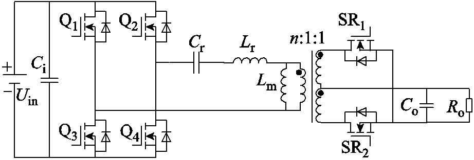
图1 全桥LLC变换器拓扑结构
Fig.1 Topology of full-bridge LLC converter
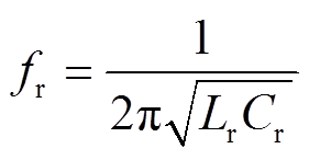
LLC变换器的谐振频率 通常用谐振电感
 与谐振电容
与谐振电容 决定的串联谐振频率表示,具体可描述为
 (1)
(1)
由于LLC变换器的工作特性随工作频率 变化而动态改变[22-23],为建立准确的动态模型,本文将变换器按
 和
和 的频率区域分析,建立大信号模型以描述其动态特性。
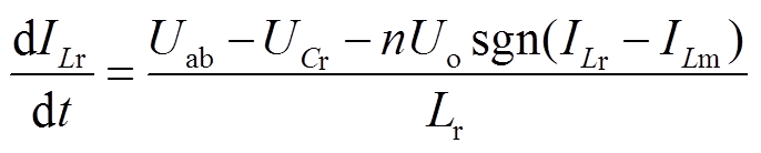
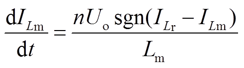
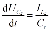
开关频率时LLC变换器的关键波形如图2a所示。此工况下全桥LLC变换器工作于连续电流模式。由于变换器的工作模态为半周期对称,因此仅对前半周期t0~t2内的电路状态进行分析。
在t0~t1阶段,谐振电流 的绝对值大于励磁电流
 的绝对值,高频变压器一、二次侧耦合,励磁电感
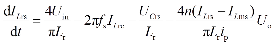
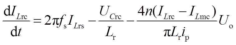
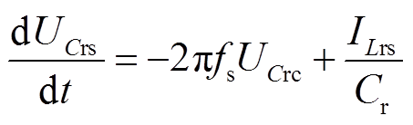
 两端电压被变换器输出电压钳位,变换器一次侧向二次侧传递能量,谐振腔中仅谐振电感和谐振电容参与谐振,此时励磁电感两端电压的方向与
 相反;在t1~t2阶段,谐振电流大于励磁电流,变压器一、二次侧耦合,励磁电感两端电压被输出电压钳位,变换器一次侧向二次侧传递能量,谐振腔中谐振电感、谐振电容参与谐振。当
 时变换器同样工作于连续电流模式,工作模态为对称的t1~t2阶段,此工况下全桥LLC变换器的动态模型与时相同,可由式(2)~式(5)表示。
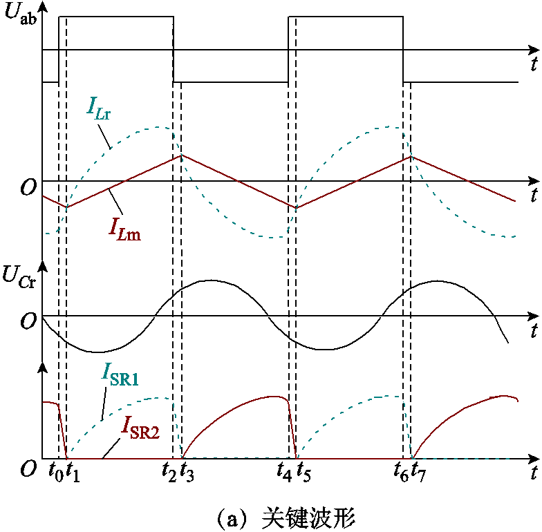
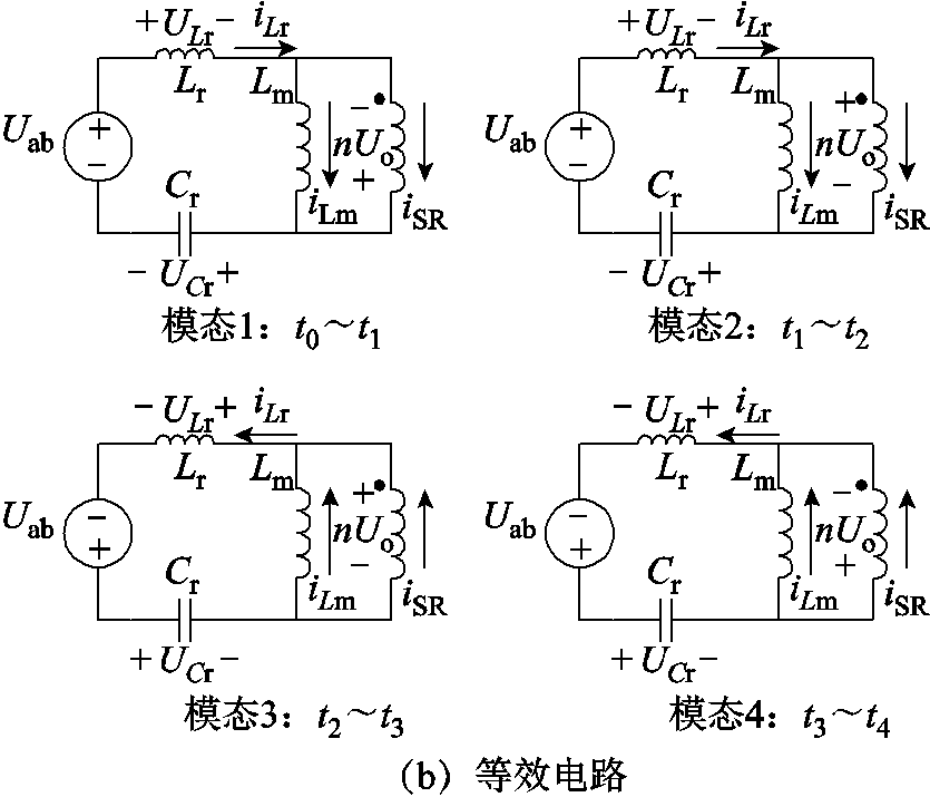
图2 全桥LLC变换器特性分析
Fig.2 Analyze of full-bridge LLC converter
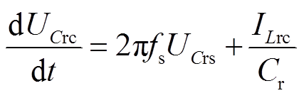
 (2)
(2)
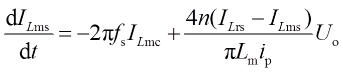
 (3)
(3)
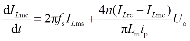
 (4)
(4)
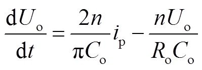
 (5)
(5)
式中,sgn(x)为符号函数。
开关频率时LLC变换器的关键波形如图3a所示。此工况下LLC变换器工作在断续电流模式。
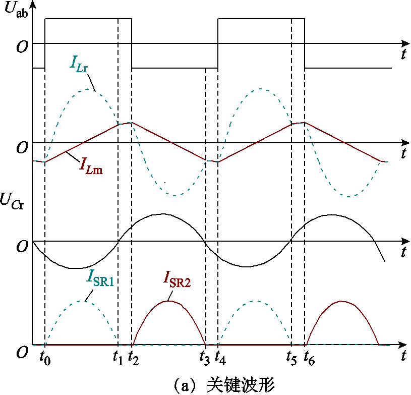
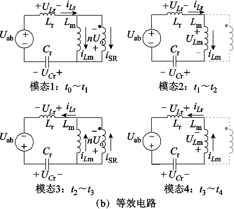
图3 全桥LLC变换器特性分析
Fig.3 Analyze of full-bridge LLC converter
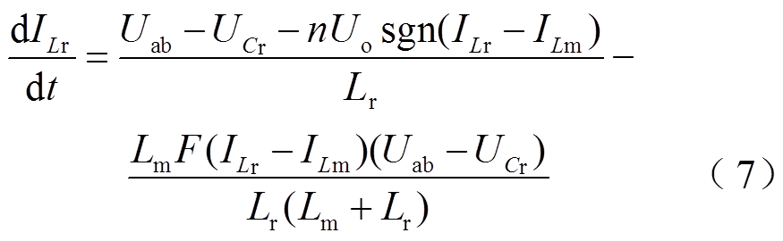
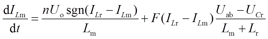
由图3b可得,在t0~t1阶段,谐振电流大于励磁电流,变压器一、二次侧耦合,励磁电感两端电压被变换器输出电压钳位,变换器一次侧向二次侧传递能量,谐振腔中仅谐振电感和谐振电容参与谐振;在t1~t2阶段,谐振电流等于励磁电流,变压器一、二次侧解耦,励磁电感两端电压不再被输出电压钳位,变换器一次侧不再向二次侧传递能量,谐振腔中谐振电感、谐振电容和励磁电感均参与谐振。综上所述,当 时,变换器在一个开关周期内具有两种等效谐振拓扑。由基尔霍夫电压定律可得,在变压器的一、二次侧耦合的阶段,与的状态方程分别与等式(2)和等式(3)相同,但是在变压器一、二次侧解耦的阶段,由于励磁电感参与谐振,其状态方程发生改变。
为了在动态模型中实现上述两种等效谐振拓扑的自动切换,从而实现全桥LLC变换器断续电流模式的准确描述,定义切换函数 满足
满足
 (6)
(6)
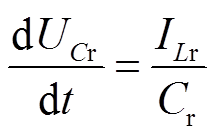
利用,当时LLC变换器的动态模型可以表示为
 (8)
(8)
 (9)
(9)
 (10)
(10)
由上述分析可得,LLC变换器在的动态模型与 时的动态模型相同,但与时的动态模型不同。由于时变换器皆运行于连续电流模式,此类工况在的动态模型中使得切换函数始终为零,即式(7)和式(8)分别与式(2)和式(3)等效。由此可得,的动态模型同样能够描述的变换器特性。因此,式(7)~式(10)即为全桥LLC变换器全工作频率范围统一的大信号非连续模型。
上述动态模型能够准确地描述全桥LLC变换器在全工作频率范围内的不同运行模式。然而,该模型是非连续的,其中存在符号函数等多种非连续函数。对于电力电子变换器的特性分析、实时仿真和控制器设计而言,这类模型意味着连续系统方法无法使用,大信号模型的连续化十分关键。本文将上述非连续模型连续化,基于拓展型双曲正切函数建立了一种全桥LLC变换器的大信号连续模型。
双曲正切函数是一种连续、平滑、可微,并且在一定值饱和的函数,通常用 表示,具体表达式为
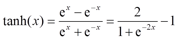 (11)
(11)
双曲正切函数的值域为(-1,1),向自变量x中注入陡度因子b,本文提出一种含陡度因子b的双曲正切函数。不同陡度因子取值的双曲正切函数与sgn函数的曲线如图4所示。
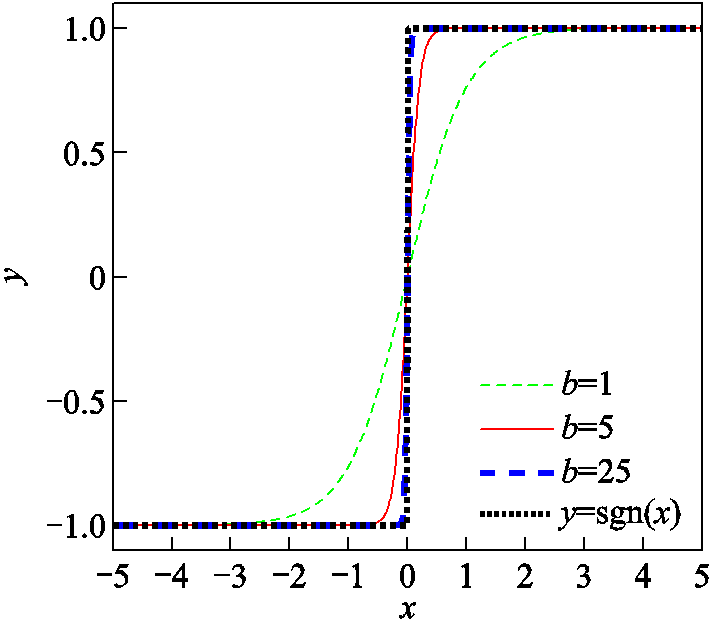
图4  与含不同陡度因子的
Fig.4 Hyperbolic tangent function with different steepness factors and symbolic function
由图4可知,陡度因子b取值越高, 函数越逼近于sgn函数,因此可利用高陡度因子的双曲正切函数实现sgn函数的近似逼近,即
 (12)
(12)
由于绝对值函数 可表示为
可表示为
 (13)
(13)
因此,绝对值函数同样可以利用含陡度因子的双曲正切函数近似逼近。
理想条件下,全桥LLC谐振变换器一次侧两桥臂中点间的电压的数学表达式为离散的开关函数,由于采用PFM调制,驱动信号在每个开关周期的占空比保持不变,可由周期型的sgn函数近似,表示为
 (14)
(14)
式中, 为输入电压;
 为角频率(
为角频率( );
); 为系统的初始相位
 ,通过改变角频率可以实现变换器开关频率变化的动态响应。
基于含陡度因子的双曲正切函数能够近似逼近sgn函数的思想,为了建立全桥LLC变换器的连续模型,采用含陡度因子的周期型双曲正切函数近似等效全桥LLC变换器初级侧两桥臂中点间电压,即
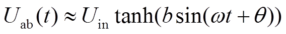 (15)
(15)
基于周期型sgn函数的 和含不同陡度因子的周期型双曲正切函数的曲线如图5所示。显然,与基于周期型sgn函数的不同,通过含陡度因子的周期型双曲正切函数描述的并非标准的方波,其根据陡度因子的取值在切换过程中具有不同的斜率。
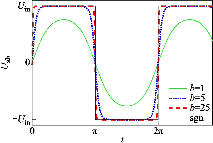
图5 周期型与含不同陡度因子的周期型
Fig.5 Periodic hyperbolic tangent functionwith different steepness factors and symbolic function
在工程应用中,的波形受实际系统中死区时间、延迟时间等因素影响,在切换过程中与双曲正切函数具有类似的斜率。因此,可通过合理设计陡度因子b的值来调整函数的斜率以使其逼近实际系统波形。相比于基于sgn函数的非连续模型,含陡度因子的双曲正切函数能够实现全桥LLC变换器一次侧两桥臂中点间电压的高准确度近似。陡度因子b的取值应充分考虑全桥LLC变换器的一次侧控制信号的死区时间、驱动延迟时间、电力电子器件的开关延迟时间和输出电压纹波要求。针对在实际系统中的特性,本文给出一种工程上可用的陡度因子b参考设计方法。
参考实际应用中对于DC-DC变换器输出电压纹波的要求,以其不大于1%的输出电压为例,将两组开关管Q1、Q4或Q2、Q3完全导通进入稳态的近似条件定义为
 (16)
(16)
LLC谐振变换器两组开关管的开关状态切换过程如图6所示。
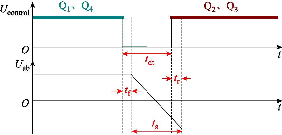
图6 全桥LLC变换器开关切换示意图
Fig.6 Diagram of switching process of full-bridge LLC converter
可以得到切换时间 满足
满足
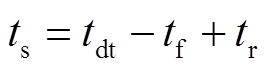 (17)
(17)
式中, 为LLC谐振变换器一次侧控制信号的死区时间;
 为驱动关断延迟时间和开关管关断延迟时间之和;
 为驱动开通延迟时间和开关管开通延迟时间之和。和可通过查阅驱动芯片和开关管的数据手册得到。综上可得
![]() (18)
(18)
式中,S为电压纹波率。根据式(18)可求得陡度因子b。实际应用中陡度因子通常取值较高,可将最后结果适当取整以简化后续分析和计算。
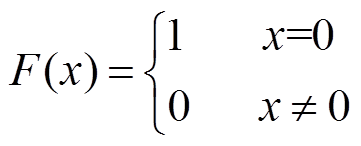
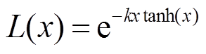
为了以连续函数准确描述LLC变换器连续模式和断续模式的自动切换,本文构建了一种含脉冲系数的双曲正切函数,即
 (19)
(19)
式中,k为脉冲系数,其决定了函数值在0和1之间的切换速度。当脉冲系数取不同值时拓展型双曲正切函数 与函数的函数图像如图7所示,当脉冲系数取值较高时有
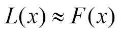 。
。
图7 与含不同脉冲系数的
Fig.7 Hyperbolic tangent function with different impulse coefficient and switching function
进而,可以通过含脉冲系数的双曲正切函数实现全桥LLC变换器的连续模式和断续模式的统一描述。
随着脉冲系数k取值的增大,拓展型双曲正切函数与切换函数的近似程度越高,基于拓展型双曲正切函数的模型对于全桥LLC变换器电流模式切换的描述越准确。然而,高脉冲系数会导致模型计算负担的增大,提高了应用难度。因此,脉冲系数的选取应平衡模型的准确性与计算负担。本文提供一种脉冲系数k的参数选取方法,在保障模型准确性的前提下尽量降低计算负担,具体选取方法如下。
由于在 处恒等于1,因此脉冲系数选取的关键是确定接近为0时
 的取值。结合实际系统中物理意义,中为全桥LLC变换器一次侧向二次侧传输的电流,即谐振电流与励磁电流的差,其在拓展型双曲正切函数中体现变换器连续电流模式或断续电流模式的状态。参考实际应用中LLC变换器二次侧整流二极管/同步整流MOSFET体二极管存在最小导通电流
 (可由数据手册中伏安特性曲线得到),选定二次电流是否大于作为全桥LLC变换器连续电流模式与断续电流模式的切换条件,因此,在二次侧电流小于时,的值应接近为0。综上可得
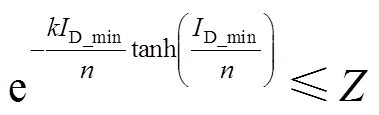 (20)
(20)
式中,n为变压器匝数比;Z为常数,其值越接近0,模型准确性越高,建议取值不大于 。据此,可根据式(20)完成脉冲系数k的选取。
基于上述含陡度因子和含脉冲系数的拓展型双曲正切函数,全桥LLC变换器的大信号连续模型可表示为
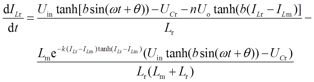 (21)
(21)

 (23)
(23)
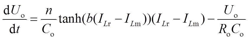 (24)
(24)
本文提出的大信号连续模型的应用条件为一次侧逆变拓扑为全桥、二次侧整流拓扑无限制的LLC变换器,该模型能够实现全桥LLC变换器在连续电流模式和断续电流模式运行特性的准确描述,即在全桥LLC变换器的全工作频率范围内均适用。值得一提的是,为了进一步提高LLC变换器的开关频率和功率密度,平面型变压器开始逐渐被应用于LLC变换器中。而平面型变压器的杂散电容对于LLC变换器的轻载特性具有一定影响。本文提出的大信号建模方法并未考虑该杂散电容。因此,本文提出的大信号连续模型在对采用平面型变压器的LLC变换器的轻载工况进行分析时,其精确度会有所降低,这也是后续针对带有平面型变压器的LLC变换器建模的研究方向。
本文提出的大信号建模方法中,利用连续的拓展型双曲正切函数近似替换非连续的切换函数以构建连续模型描述断续电流模式中两种不同的等效电路拓扑。而模型的误差主要由该拓展型双曲正切函数引入。不同于,存在大于0且小于1的情况,在此情况下提出的模型不能完全准确地描述LLC变换器的等效电路拓扑,从而导致模型的误差。特别是,当变换器二次侧电流在0和二极管最小导通电流之间时,的值不能被近似为0或1,此时提出的模型与LLC变换器任意模式等效电路拓扑均不对应,导致模型的误差增大。因此,对于提出的模型,其误差的大小主要取决于每个开关周期内二次电流在大于0和小于之间的时间与整个开关周期时间的比例。该比例越低,则提出的模型误差越小。相同输出工况下,当开关频率小于谐振频率时,LLC变换器工作在断续电流模式,随着开关频率降低,每个开关周期内二次电流为0的时间增加,从而使得二次电流在大于0和小于之间的时间与整个开关周期时间的比例减小;而当开关频率大于谐振频率时,LLC变换器工作在连续电流模式,二次电流在大于0和小于之间的时间与整个开关周期时间的比例基本不变,因此模型的误差变化较小。综上所述,即便在开关频率远离谐振频率的工况,提出的模型仍具有较低的误差。
为了验证基于拓展型双曲正切函数的LLC变换器大信号模型的准确性和有效性,本文基于图1所示的全桥LLC谐振变换器拓扑,对建立的大信号连续模型进行仿真与实验验证,具体参数见表1。基于函数陡度因子设计方法和脉冲系数选取原则,得到陡度因子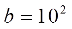 ,脉冲系数
,脉冲系数 。
。
表1 LLC变换器关键参数
Tab.1 Key parameters of LLC converter
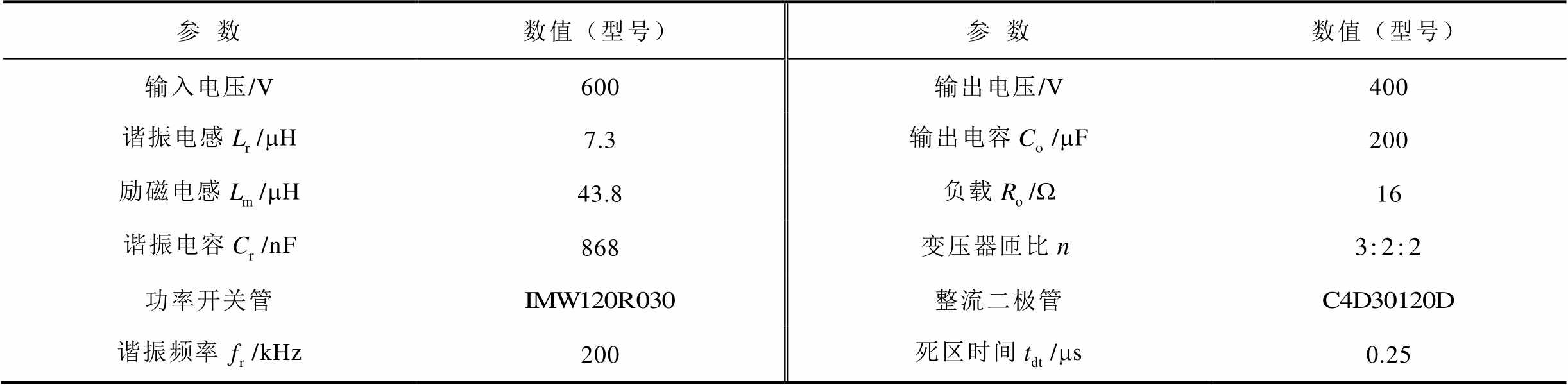
参数数值(型号)参数数值(型号) 输入电压/V600输出电压/V400 谐振电感/mH7.3输出电容/mF200 励磁电感/mH43.8负载/W16 谐振电容/nF868变压器匝比 功率开关管整流二极管 谐振频率/kHz200死区时间/ms0.25
本文利用Matlab分别建立全桥LLC变换器的基于扩展描述函数法的大信号模型和基于拓展型双曲正切函数的大信号模型,利用Simulink搭建图1所示的全桥LLC变换器仿真模型。
图8~图10分别为上述模型在小于、等于和大于谐振频率时电流、电压的关键波形,ID为流过二次侧同步整流器的电流。其中,基于拓展型双曲正切函数的大信号连续模型依据式(21)~式(24)建立,基于扩展描述函数法的模型依据文献[14]所提出的方法建立,具体模型为

图8 全桥LLC变换器仿真模型关键波形( )
)
Fig.8 Waveform diagram of simulation models of full-bridge LLC converter()
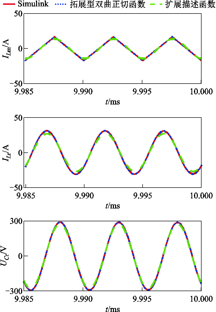
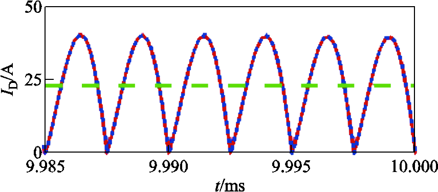
图9 全桥LLC变换器仿真模型关键波形( )
)
Fig.9 Waveforms of simulation models of full-bridge LLC converter( )
)
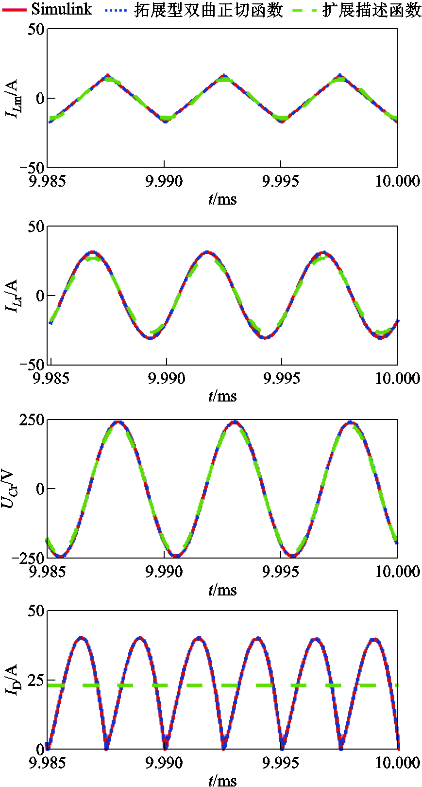
图10 全桥LLC变换器仿真模型关键波形( )
)
Fig.10 Waveforms of simulation models of full-bridge LLC converter()
 (25)
(25)
 (26)
(26)
 (27)
(27)
 (28)
(28)
 (29)
(29)
 (30)
(30)
 (31)
(31)
式中, 、
、 分别为谐振电流的正弦分量和余弦分量;
 、
、 分别为谐振电容电压的正弦分量和余弦分量;
 、
、 分别为励磁电流的正弦分量和余弦分量;
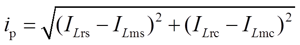 。
。
在图8~图10中,实线(红色)为通过Simulink搭建的电路模型的仿真曲线,虚线(绿色)为基于扩展描述函数法大信号模型的仿真曲线,点线(蓝色)为本文提出的基于拓展型双曲正切函数的大信号模型仿真曲线。由此可知,全桥LLC变换器的Simulink模型和本文提出的大信号模型在 的断续电流模式和
 的连续电流模式的仿真曲线都是高度一致的,因此,本文提出的大信号模型实现了LLC变换器连续电流模式和断续电流模式的准确描述。而基于扩展描述函数法所建立的大信号模型与Simulink搭建的电路模型的仿真曲线是不一致的,尤其在的工况下(断续电流模式)区别更为明显。并且,基于扩展描述函数法的大信号模型将变换器二次电流波形近似为一条直线,而本文所建模型能够提供二次电流高准确性的状态信息,便于同步整流方法的设计。因此,与扩展描述函数法建立的大信号模型相比,本文所建的大信号模型对于LLC变换器全工作频率范围运行特性描述具有更高的准确性。
以LLC变换器Simulink模型的仿真结果为基准对提出的大信号连续模型在不同频率区域(大于、等于或小于谐振频率)的方均误差进行计算,结果见表2。可以看出,在全工作频率范围内,本文提出的大信号连续模型均具有较高的准确度。相比于轻载工况,重载工况下本文提出的模型对LLC变换器运行特性的描述更为准确。
仿真时间t=10ms,LLC变换器大信号连续模型与本文提出的模型的计算耗时和内存占用情况见表3。虽然基于本文提出的大信号连续模型的计算耗时和资源消耗略高于文献[14]和文献[17]中的大信号连续模型。但从图8~图10中可以看出,本文提出的大信号连续模型相比于现有LLC变换器大信号连续模型则具有更高的准确度。
表2 提出模型/Simulink模型-方均根误差
Tab.2 Proposed model/Simulink model – RMSE
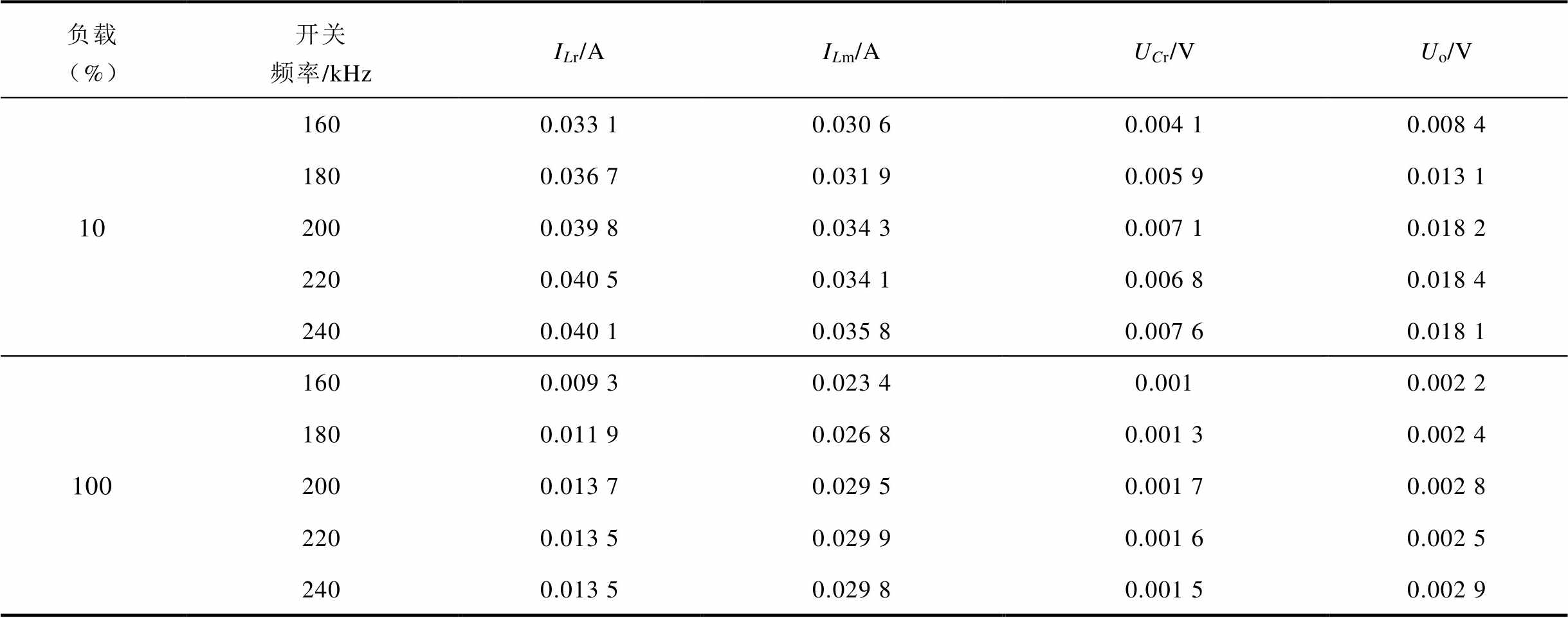
负载 (%)开关频率/kHzILr/AILm/AUCr/VUo/V 101600.033 10.030 60.004 10.008 4 1800.036 70.031 90.005 90.013 1 2000.039 80.034 30.007 10.018 2 2200.040 50.034 10.006 80.018 4 2400.040 10.035 80.007 60.018 1 1001600.009 30.023 40.0010.002 2 1800.011 90.026 80.001 30.002 4 2000.013 70.029 50.001 70.002 8 2200.013 50.029 90.001 60.002 5 2400.013 50.029 80.001 50.002 9
表3 模型计算耗时和内存占用
Tab. 3 Computation time and memory usage of model
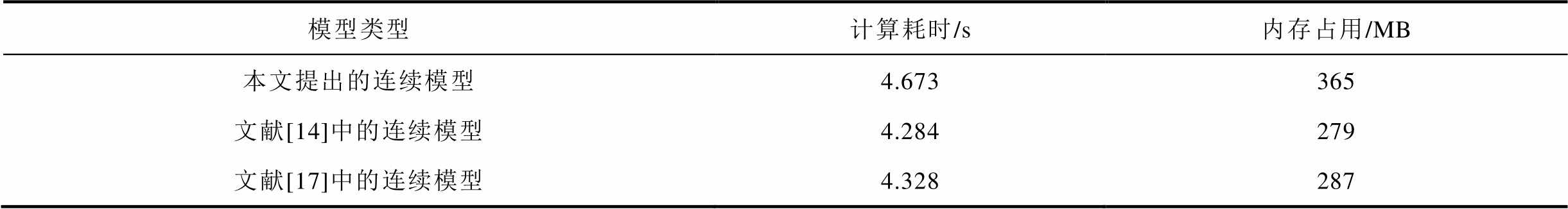
模型类型计算耗时/s内存占用/MB 本文提出的连续模型4.673365 文献[14]中的连续模型4.284279 文献[17]中的连续模型4.328287
图11验证了在输入电压突变条件下,提出的大信号模型的动态特性。在t=3ms时,输入电压由600V降至400V,输出电压做出相应响应。由图11可知,基于拓展型双曲正切函数的大信号模型的瞬态响应与基于Simulink的电路仿真模型结果基本一致,即所提出LLC变换器大信号模型可以准确描述系统的动态特性。
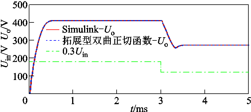
图11 提出的大信号模型动态特性图
Fig.11 Diagram of dynamic characteristics of proposed model
本文提出的基于拓展型双曲正切函数的大信号模型是连续的,便于应用连续系统的方法对LLC变换器进行特性分析、实时仿真和控制器设计。虽然基于扩展描述函数法建立的连续模型与本文提出的大信号连续模型相比更易于进行线性化和小信号扰动,但其模型的阶数通常较高,而本文提出的大信号模型则具有更低的阶数,并具有更高的准确度。
为了进一步验证本文提出的大信号模型的有效性,搭建了一台5kW全桥LLC变换器样机进行实验验证,该样机采用TMS320F28335作为数字控制器,二次侧采用二极管整流。图12为具体实验环境。不同频率区间 、
、 、
、 的实验波形如图13~图15所示。
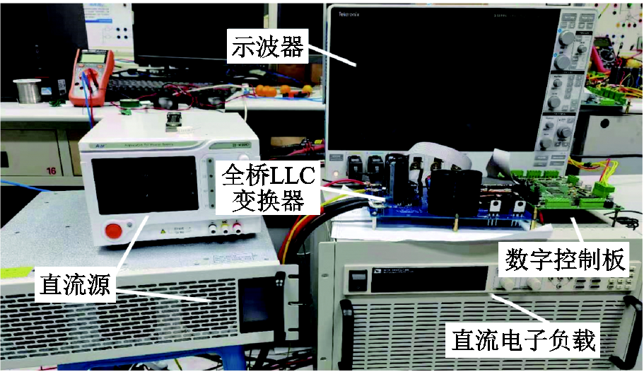
图12 实验环境
Fig.12 Experimental environment

图13 全桥LLC变换器实验波形
Fig.13 Experimental waveforms of full-bridge LLC converter
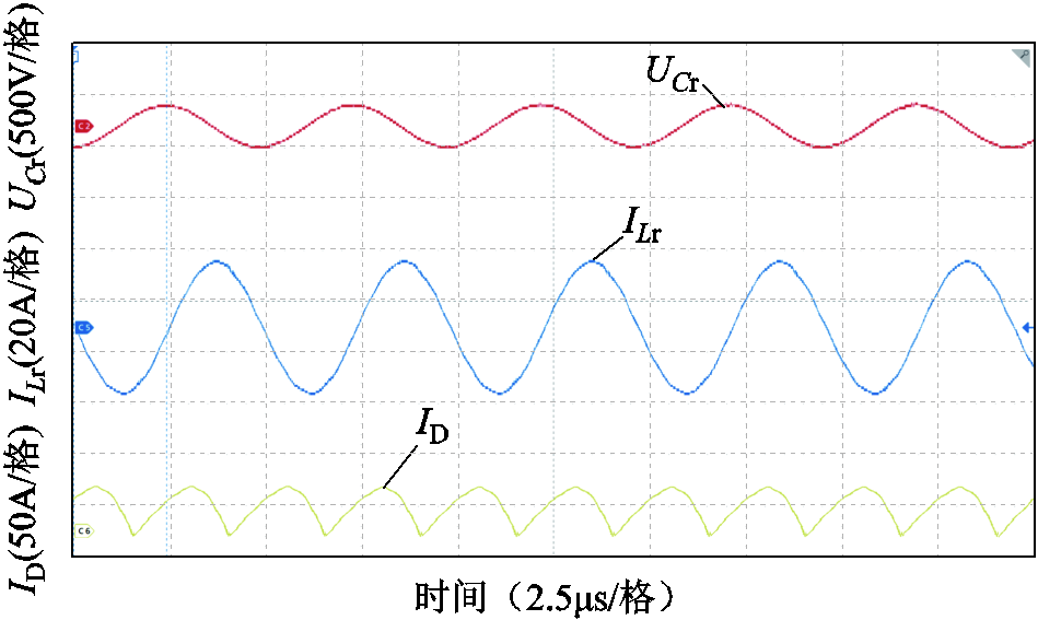
图14 全桥LLC变换器实验波形
Fig.14 Experimental waveforms of full-bridge LLC converter
由图13~图15可知,基于拓展型双曲正切函数的大信号模型和基于Simulink的模型的仿真结果与全桥LLC变换器的实际运行状态相同,进一步验证了本文提出大信号模型的有效性。上述仿真和实验结果验证了本文提出模型的准确性和有效性,所提出的基于拓展型双曲正切函数的大信号模型实现了全桥LLC变换器全工作频率范围内静/动态特性的准确描述。
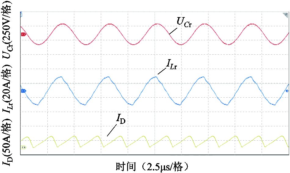
图15 全桥LLC变换器实验波形
Fig.15 Experimental waveforms of full-bridge LLC converter
为了以连续模型准确地实现对LLC变换器多种运行模式的统一描述,本文提出了一种基于拓展型双曲正切函数的全桥LLC变换器大信号建模方法。基于此方法建立的大信号模型不包含任何非连续函数,进而可以直接应用连续系统的方法对LLC变换器进行动态特性分析、实时仿真和控制器设计。同时,该模型考虑了死区时间、器件开关延时等参数影响,能够准确地实现LLC变换器连续电流模式与断续电流模式的统一描述。相比于现有的LLC变换器大信号连续模型,该模型具有更低的阶数,并且具有更高的准确度。此外,基于拓展型双曲正切函数的大信号模型在时域中能够给出LLC变换器二次电流高准确性的状态信息,便于同步整流方案的设计。通过仿真和实验验证了所提出大信号建模方法的准确性和有效性。
参考文献
[1] 孙加祥, 吴红飞, 汤欣喜, 等. 基于整流侧辅助调控的交错并联LLC谐振变换器[J]. 电工技术学报, 2021, 36(10): 2072-2080.
Sun Jiaxiang, Wu Hongfei, Tang Xinxi, et al. Interleaved LLC resonant converter with auxiliary regulation of rectifier[J]. Transactions of China Electrotechnical Society, 2021, 36(10): 2072-2080.
[2] 陈梦颖, 王议锋, 陈庆, 等. 一种可变结构型高效宽增益多谐振软开关直流变换器[J]. 电工技术学报, 2021, 36(20): 4225-4236.
Chen Mengying, Wang Yifeng, Chen Qing, et al. A variable topology multi-resonant soft-switching DC-DC converter with high efficiency and wide gain[J]. Transactions of China Electrotechnical Society, 2021, 36(20): 4225-4236.
[3] 周国华, 冷敏瑞, 李媛, 等. 开关变换器及其控制环路的建模综述[J]. 中国电机工程学报, 2020, 40(1): 183-199, 386.
Zhou Guohua, Leng Minrui, Li Yuan, et al. A review on modeling of switching converters and their control loops[J]. Proceedings of the CSEE, 2020, 40(1): 183-199, 386.
[4] Bhat A K S. A unified approach for the steady-state analysis of resonant converters[J]. IEEE Transactions on Industrial Electronics, 1991, 38(4): 251-259.
[5] De Simone S, Adragna C, Spini C, et al. Design-oriented steady-state analysis of LLC resonant converters based on FHA[C]//2006International Symposium on Power Electronics, Electrical Drives, Automation and Motion, Taormina, Italy, 2006: 200-207.
[6] 丁超, 李勇, 姜利, 等. 电动汽车直流充电系统LLC谐振变换器软开关电压边界分析[J]. 电工技术学报, 2022, 37(1): 3-11.
Ding Chao, Li Yong, Jiang Li, et al. Analysis of soft switching voltage boundary of LLC resonant converter for EV DC charging system[J]. Transactions of China Electrotechnical Society, 2022, 37(1): 3-11.
[7] Ivensky G, Bronshtein S, Abramovitz A. Approximate analysis of resonant LLC DC-DC converter[J]. IEEE Transactions on Power Electronics, 2011, 26(11): 3274-3284.
[8] Liu Jianqiang, Zhang Jiepin, Zheng T Q, et al. A modified gain model and the corresponding design method for an LLC resonant converter[J]. IEEE Transactions on Power Electronics, 2017, 32(9): 6716-6727.
[9] Agarwal V, Bhat A K S. Small signal analysis of the LCC-type parallel resonant converter using discrete time domain modeling[C]//Proceedings of 1994 Power Electronics Specialist Conference-PESC'94, Taipei, China, 1994: 805-813.
[10] Song Zhanfeng, Zhou Fengjiao. Observer-based predictive vector-resonant current control of permanent magnet synchronous machines[J]. IEEE Transactions on Power Electronics, 2019, 34(6): 5969-5980.
[11] Qin Hengsi, Kimball J W. Generalized average modeling of dual active bridge DC-DC converter[J]. IEEE Transactions on Power Electronics, 2012, 27(4): 2078-2084.
[12] Shang Fei, Wu Haowen, Niu Geng, et al. Dynamic analysis and control approach for a high-gain step-up converter for electrified transportation[J]. IEEE Transactions on Transportation Electrification, 2017, 3(3): 656-667.
[13] Menke M F, Seidel Á R, Tambara R V. LLC LED driver small-signal modeling and digital control design for active ripple compensation[J]. IEEE Transactions on Industrial Electronics, 2019, 66(1): 387-396.
[14] Buccella C, Cecati C, Latafat H, et al. Observer-based control of LLC DC/DC resonant converter using extended describing functions[J]. IEEE Transactions on Power Electronics, 2015, 30(10): 5881-5891.
[15] 徐玉珍, 郭跃森, 林维明. 一种具有自动均流特性的并联LLC谐振变换器[J]. 中国电机工程学报, 2018, 38(22): 6671-6683.
Xu Yuzhen, Guo Yuesen, Lin Weiming. A parallel LLC resonant converter with automatic current sharing characteristics[J]. Proceedings of the CSEE, 2018, 38(22): 6671-6683.
[16] Tian Shuilin, Lee F C, Li Qiang. Equivalent circuit modeling of LLC resonant converter[C]//2016 IEEE Applied Power Electronics Conference and Exposition, Long Beach, CA, USA, 2016: 1608-1615.
[17] Tian Shuilin, Lee F C, Li Qiang. Equivalent circuit modeling of LLC resonant converter[J]. IEEE Transactions on Power Electronics, 2020, 35(8): 8833-8845.
[18] Mansour A, Hajer M, Faouzi B, et al. Analysis and modeling of LLC resonant converter used in electric vehicle[C]//2019 International Conference on Advanced Systems and Emergent Technologies (IC_ASET), Hammamet, Tunisia, 2019: 357-362.
[19] Lu Yimin, Huang Xianfeng, Huang Yizheng, et al. Sigmoid function model for a PFM power electronic converter[J]. IEEE Transactions on Power Electronics, 2020, 35(4): 4233-4241.
[20] Hsu J D, Ordonez M, Eberle W, et al. LLC synchronous rectification using resonant capacitor voltage[J]. IEEE Transactions on Power Electronics, 2019, 34(11): 10970-10987.
[21] Kim J H, Kim C E, Kim J K, et al. Analysis on load-adaptive phase-shift control for high efficiency full-bridge LLC resonant converter under light-load conditions[J]. IEEE Transactions on Power Electronics, 2016, 31(7): 4942-4955.
[22] 焦健, 郭希铮, 游小杰, 等. LLC谐振变换器的改进型电流解析方法[J]. 电工技术学报, 2021, 36(23): 5002-5013.
Jiao Jian, Guo Xizheng, You Xiaojie, et al. An improved current analytical method for LLC resonant converter[J]. Transactions of China Electrotechnical Society, 2021, 36(23): 5002-5013.
[23] 袁义生, 易尘宇, 彭能. L-R复合调制T型半桥LCC谐振变换器[J]. 电工技术学报, 2022, 37(4): 892-904.
Yuan Yisheng, Yi Chenyu, Peng Neng. T-type half-bridge LCC resonant converter with L-R composite modulation[J]. Transactions of China Electrotechnical Society, 2022, 37(4): 892-904.
Abstract The accuracy of the continuous model is very important for the characteristic analysis, real time simulation and controller design of power electronic converter. LLC resonant converter operates in continuous current mode and discontinuous current mode respectively in different operating frequency intervals due to its unique cavity structure. Therefore, it is difficult to establish a continuous model which can realize the unified description of various operating modes of LLC resonant converter. Therefore, a large signal modeling method for full bridge LLC resonant converter based on extended hyperbolic tangent function is proposed to establish an accurate large signal continuous model. Firstly, the operating characteristics of full bridge LLC resonant converters in each frequency range are analyzed. Based on this analysis, a large signal discontinuity model of full bridge LLC resonant converter is established by using the symbolic function, the absolute value function and the defined operation mode switching function. The discontinuity model can realize the unified description of continuous current mode and discontinuous current mode of full bridge LLC resonant converter. Then, two kinds of extended hyperbolic tangent functions including steepness factor and pulse coefficient are constructed, and the standardized selection methods of steepness factor and pulse coefficient are provided. By changing the steepness factor and pulse coefficient, the dead time and device switching delay time of the full bridge LLC resonant converter can be approximated with high precision, thus realizing accurate large signal modeling. Based on the extended hyperbolic tangent function, the discontinuous model is continuous, and the large signal continuous model of the full bridge LLC converter is established. Based on this model, the method of continuous system can be applied directly to realize the characteristic analysis and controller design of converter. At the same time, compared with the existing LLC resonant converter large signal continuous model, the model has lower order and higher accuracy. In addition, the large signal continuous model established in this paper can provide highly accurate switching information of the secondary power components of the full bridge LLC resonant converter in the time domain, which is convenient to be used as a reference for the design of synchronous rectifier controller. Finally, the accuracy and effectiveness of the proposed large signal continuous model are verified by building the MATLAB / Simulink simulation model and the experimental prototype with rated power of 5kW. In the full range of operating frequency, the large signal continuous model is presented with high accuracy. Compared with the light load condition, the model proposed in the heavy load condition can describe the operating characteristics of the full bridge LLC resonant converter more accurately. The computing time and resource consumption are slightly higher than the existing large signal continuous model, but the proposed large signal continuous model has higher accuracy. Although the continuous model based on the extended description function method is easier to carry out linearization and small signal perturbation than the proposed large signal continuous model, the order of the model is usually higher, while the proposed large signal continuous model proposed has a lower order. In addition, the proposed large signal continuous model can accurately describe the dynamic characteristics of the full bridge LLC resonant converter.
Keywords:Full-bridge LLC converter, continuous system, large-signal model, extended hyperbolic tangent function
DOI:10.19595/j.cnki.1000-6753.tces.210933
中图分类号:TM46
孙城皓 男,1996年生,博士研究生,研究方向为谐振变换器的建模与控制。E-mail:1910243@stu.neu.edu.cn
孙秋野 男,1977年生,教授,博士生导师,研究方向为能源互联网的建模与优化运行、电力电子化电力系统等。E-mail:sunqiuye@ise.neu.edu.cn(通信作者)
国家重点研发计划变革性课题(2018YFA0702200)和国家自然科学基金(62073065)资助项目。
收稿日期 2021-06-30
改稿日期 2022-04-21
(编辑 赫蕾)