 (1)
(1)Abstract Multi-physics fields inside high-speed electrical machines are strongly coupled and may even conflict with each other. Therefore, design of the high-speed machines is extremely constrained by these fields. Moreover, power converters have limited current and voltage, by which the machine design is also constrained. All these constraints become further significant if the machines are of high power. Therefore, it is challenging to achieve a feasible solution of machine design. As a study case, design and optimization of a 350kW and 13.5kr/min interior permanent magnet synchronous motor (PMSM) is presented in this paper. Principal of matching the permanent magnet flux linkage with the winding inductances for various operation conditions is investigated, so that both the voltage and current limits of the power converter can be satisfied. Then, related design aspects are addressed, especially, the rotor configuration considering the electromagnetic performance, mechanical stress and rotor dynamics is studied with finite element methods (FEM), and the thermal behavior is studied with computational fluid dynamics (CFD), demonstrating the comprehensive procedure of multi-physics design.
Keywords: High-speed permanent magnet synchronous motor, multi-physics design, power converter constraint, rotor configuration, thermal behavior
High-speed permanent magnet synchronous machines (PMSMs) are attractive candidates for many applications due to their inherent merit of high power density[1-5] which is meanwhile accompanied by the drawback of high loss density. Besides, high-speed electrical machines can form direct drive (DD) systems with high-speed loads, which not only reduce the weight and volume, but also enhances the system efficiency and reliability[6-7]. Therefore, they have found extensive applications, such as EV traction motors, fuel cell air compressors[8-9], turbine generators for exhaust energy recycling[10], and electrically assisted turbo (EAT) charger [11], etc. Large power high-speed PMSMs are also used in gas turbine systems for ships, fly wheel storage systems for metros[12], and many others.
Clearly, multi-physics fields exist and are strongly coupled in the high-speed PMSMs, hence, variation of each design parameter of the machines may have different and even conflicting effects on these fields[1]. The coupling and conflicting become more significant if the machines are of high power (e.g., more than 100kW) or of very high speed (e.g., more than 100kr/min). Therefore, design of the high-speed PMSMs is strictly limited by the multi-physics constraints[13-14]. Moreover, power converters for the high-speed machines, such as for the vehicle applications, usually have limits of volume and weight, as well as limits of voltage and current capacity[15]. Therefore, it is uneasy to get a feasible solution of machine design through the traditional step-by-step calculation. It is always challenging to optimize the high-speed PMSM design when taking all constraints of multi-physics fields and the power converter limits into account[16].
Considering the centrifugal force on the magnets, the surface-mounted permanent magnet (SPM) rotor structure with retaining sleeve is usually adopted for high-speed PMSMs[16-21]. However, the retaining sleeve is complicated to manufacture and install, and may make the electromagnetic air gap unexpectedly large. Selection of the sleeve material is also critical[22-23]. Conductive metallic sleeves can cause extra eddy current loss and even high temperature rise. Whilst, non-metallic sleeves usually have low thermal conductivity, thus are unsatisfactory for heat dissipation from the rotor. Moreover, the non-metallic sleeves such as carbon fiber sleeves usually have lower thermal expansion coefficient than the magnets and rotor core, hence will suffer from extraordinary thermal stress when the rotor temperature increases. These issues become especially severe for the large-power high-speed SPMSM. On the other hand, for the interior permanent magnet (IPM) rotor structure, the rotor lamination core can retain the magnets directly, eliminating the retaining sleeve. However, the mechanical strength of the silicon-steel lamination is lower than that of most retaining sleeve materials such as Titanium alloy, Inconel or carbon fiber, hence the circumferential and radial bridges on the rotor laminations must be sufficiently thick, which will largely reduce the amplitude and may even distort the distribution waveform of the PM-excited air gap field. Therefore, compared with the SPM structure, the IPM rotor structure is generally more complicated for design but simpler for manufacturing[24]. Hence, in this paper, the IPM structure, which is generally more complicated than the SPM structure, is taken as an example to study the high-speed large-power PMSM design. Most study results concluded from the IPM machines are also applicable for the SPM machines.
Clearly, multi-physics constraints in the high-speed machine as well as the voltage and current constraints of the power converter must be comprehensively considered during the machine design. Lots of related studies have been reported. In Ref.[11] and Ref.[15] the power converter constraints were analyzed in detail. However, it was not mentioned how to satisfy the constraints through the machine design. In this paper, the problem of the power converter constraints will be solved using a base machine which has a unit length, one turn per coil and one parallel branch of the windings. Initial electromagnetic design of the base machine will be presented in section 1, and design derivation from the base machine to the real machine will be detailed in section 2. Moreover, in most papers on the topic of high-speed machine design such as Ref.[8-9,13,18] and many others, various fields performance was analyzed. However, coupling of various fields was hardly demonstrated, as those fields were considered separately. In Ref.[16] multi-physics and multi-objective optimization was reported, but such optimization was simply carried out with a commercial software, whilst the relationship between the multi-physics performances and the design parameters were not presented. Obviously, revealing these relationships helps to understand and design the machine better. Therefore, in this paper, the rotor stress and rotor dynamics versus the rotor structure and parameters will be presented in section 3 and 4, respectively, and the machine thermal behavior will be presented in section 5.
Clearly, the process of sections 1 and 2 can bring a rough design which satisfies the power converter constraints, whilst a single process from section 3 to section 5 can only analyze the machine multi-physics performance step by step, but cannot ensure a satisfactory design of all electromagnetic, mechanical and thermal requirements. Therefore, a workflow for multi-physics iterative analysis, design and validation will be proposed in section 6, so that an optimal design can be essentially achieved.
Ratings of the studied IPMSM are 10kr/min and 350kW, with the ability of constant power operation up to 13.5kr/min. The frame size should be chosen considering the proposed water-cooling condition. It is known that motor size is directly related to its maximum output torque, which is 335N·m for the investigated PM motor, and also influenced by its pole number (especially when the pole number is small and stator yoke is thick). Therefore, it is necessary to decide the pole number of the machine before choosing the frame size.
On one hand, considering the switching frequency of the power electronic devices being 8kHz, which is common for devices at this power level, it is recommended to limit the fundamental electric frequency below 500Hz, so as to keep the carrier ratio of power converter over 16, and meanwhile to limit the stator core loss. On the other hand, it is preferred to have more pole-pairs to have a thinner stator yoke. Finally, the pole number is decided as 4, with the fundamental electric frequency of 450Hz at 13.5kr/min.
In order to determine the frame size, the Chinese standard induction motors are set as the benchmark. The frame of a 90kW 4-pole induction motor is chosen, since its rated torque is around 580N·m, which is suitable for a high-speed motor with the rated torque of 335N·m, considering the higher operating frequency and loss density. As a result, the frame bore diameter is 430mm considering the water-cooling jacket.
A stator with 48 slots and 10-slot short-pitch distributed windings is applied, which can restrain both the 5th and 7th space harmonics of stator magnetic motive force (MMF) effectively. Initial finite element analysis (FEA) shows that the torque ripple (peak-peak value over mean value) under the rated working condition is less than 5%, which is lower than that with 36 or 60 slots.
Considering the maximum electric frequency of 450Hz, thin wires should be used to reduce the AC winding resistance. However, since the penetration depth of copper wire at 450Hz is 3mm, wires with diameter of 1mm are thin enough to reduce the skin effect, and also are easy for winding manufacturing.
Usually, the flux density of high-speed motors is not required to be very high, hence, large air gap length is allowed. There are many merits to design a large air gap in a high-speed motor. First, rotor eddy current loss and cogging torque due tothe slot effect can be notably reduced. Second, high-speed motors usually have a large armature impedance due to the high operating frequency, causing a high voltage drop on the impedance. Larger air gap helps to reduce the armature inductance, and consequently the impedance voltage drop as well as the armature reaction field. Third, the magnetic rotor is easier to be installed inside the stator bore, and is less sensitive to the concentricity error due to imperfect assembly.
For the high-speed SPM machines, the magnets are in whole pieces, protected by a retaining sleeve, so the rotor can be very small and compact, with a split ratio typically less than 0.5[16-20]. However, for the IPM machines, the centrifugal forces of the magnets need to be undertaken by the rotor core laminations, therefore the magnets are usually in smaller pieces, and there is flux leakage due to the ribs and bridges of the rotor laminations. Therefore, the rotor has to be larger to provide the same level of rotor flux. Furthermore, the rotor diameter is limited by the tolerable peripheral speed, which is usually no more than 230m/s for the IPM motors[2]. In this study, rotor dimensions are mainly refined by the mechanical stress constraint. In order to establish sufficient PM flux, the diameter of the magnets’ outer surface is set as 224mm, and the rotor outer diameter is determined as 236mm according to the mechanical requirements, with the maximum peripheral speed being 167m/s, which will be further explained in the following sections.
If a large-power electrical machine is fed with the mains power supply, high voltage can be used so as to reduce the current. However, when the machine is driven with a power converter, both voltage and current have to be determined according to power supply and to the power converter capacity. Therefore, the machine parameters must be carefully designed and validated to ensure the feasibility of operation under all the constraints by the power converter.
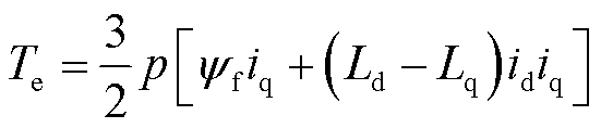
During the machine design, concerned parameters include: the flux linkage induced by the PM (yf), the d-axis and q-axis armature inductances (Ldand Lq). For a given PMSM, the operating curve of id and iq to achieve a required torque Temeets
(1)
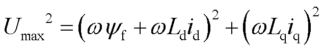
where p is the pole-pair number; id and iq are the d-axis and q-axis armature currents, respectively. The voltage limit is
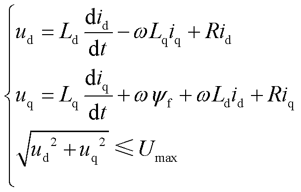 (2)
(2)
where R is the phase resistance of stator windings, which is negligible for large-power PMSM; w is the electric angular frequency; and Umax is the maximum amplitude of armature phase voltage, which is Udc/ for a voltage source inverter with the DC-link voltage of Udc and the linear pulse width modulation (PWM). The current limit is
 (3)
(3)
where Imax is the current capacity of the power converter, and, it is the maximum amplitude of the sinusoidal armature currents.
The PM flux linkage should be determined within a reasonable range at the design stage, whilst, either insufficient or oversized PM flux linkage can lead to failure in satisfying the voltage and ampere constraints. On one hand, if the PM flux linkage is insufficient, more armature currents are required to produce sufficient torque. With the given PM flux linkage and armature inductances, as shown in Fig.1a, the (green) solid curve represents the operating curve of id and iq which can produce the required torque at 10kr/min (i.e., the target torque curve). The shadowed area represents the feasible operating area at this speed, which is within both the voltage limit ellipse (the orange dashed line) and the current limit circle (the pink dash-dotted line). These two limit curves are decided by the power converter constraints. It can be seen that the (green) solid curve does not go through the shadowed area, since the target torque curve is too far away due to the insufficient PM flux linkage. On the other hand, if the PM flux linkage is oversized, the back-EMF of the motor is too high, so that more negative d-axis current is required to weaken the field and restrain the armature voltage, i.e., the voltage limit ellipse moves to the left, as shown in Fig.1b. Therefore, the shaded area within both the voltage limit ellipse and the current limit circle is too small. Although the green solid curve gets lower due to the larger PM flux linkage, it does not go through the shaded area, either. Therefore, there is no feasible solution to produce enough torque. As a result, the PM flux linkage should be determined neither too small nor too large, as shown in Fig.1c, so that both torque requirement and voltage limitation are satisfied, still with sufficient current margin. In Fig.1c, any point on the sector of the green target torque curve inside the shaded area is workable. For this case, the maximum torque per ampere (MTPA) working point is not inside the shaded area, hence, flux-weakening control is needed so as to move the working point from the “cross” (i.e., the MTPA working point) to the “small circle” (i.e., a flux-weakening point). Of course, the working point can move slightly further to the left along the target torque curve.
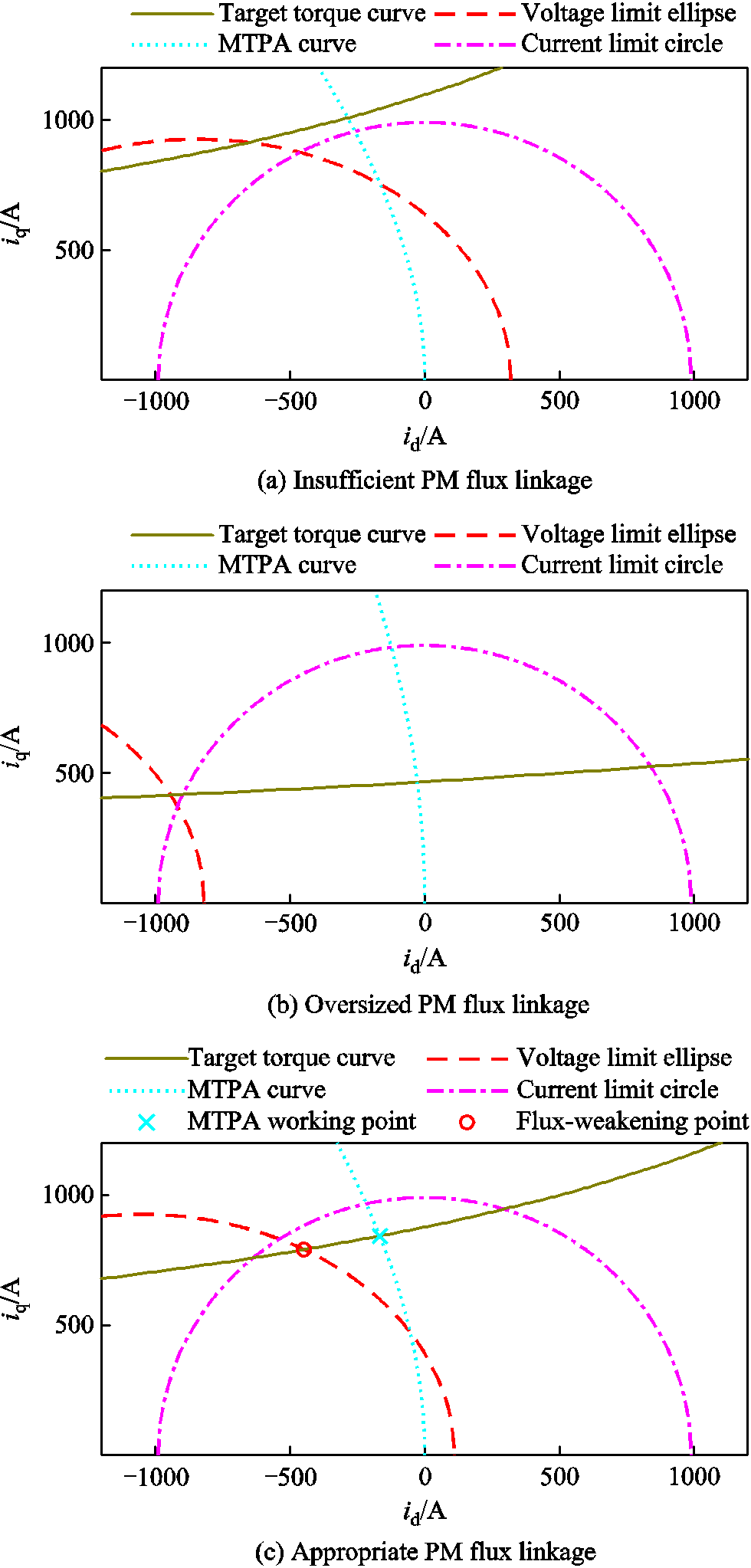
Fig.1 Various working conditions with different PM flux linkage
The armature inductance is also critical for the high-speed machines. On one hand, when operating below the base speed (without flux-weakening control), smaller armature inductance is desired to reduce thearmature impedance voltage drop and hence to better utilize the voltage of power supply. On the other hand, when operating at maximum speed with flux-weakening control, larger armature inductance is desired to weaken the flux with a smaller d-axis current, otherwise the current limitation may be exceeded[15]. Since the relationship between the armature inductances at d-axis and q-axis largely depends on the rotor structure, which is already defined by the mechanical pre-design for the studied motor, the ratio of the q-axis inductance to the d-axis one (called saliency ratio) can be regarded as a constant. In the following calculation, this ratio is determined as 1.258 according to some preliminary FEM analysis.
In order to concretize the constraints mentioned above, the feasible range and relationship between the PM flux linkage and the armature inductance will be depicted through numerical calculation. When a PMSM is working at high speed, with armature voltage fully utilized, its armature currents are directly determined by the torque requirement Eqn.(1) and the voltage limitation equation which at the steady state can be expressed as Eqn.(4), where the winding resistance is neglected.
 (4)
(4)
Meanwhile, the armature-current amplitude is further limited as Eqn.(5) which is stricter than that in Eqn.(3).
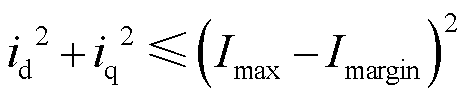 (5)
(5)
Here, Imargin is the current margin, so as to be tolerant of the unexpected changes of the machine parameters. In this study, Umax is 294V since Udc is 510V, Imax is 990A, while Imargin is set as 28A. By solving the three Eqns.(1), (4) and (5), the upper and lower bounds of the PM flux linkage (yf,upper and yf,lower) under certain armature inductances can be derived, as shown in Fig.2. Here, the armature inductances are not directly expressed with Ld and Lq, instead, they are expressed with the average armature inductance (Ld+Lq)/2 and the saliency ratio, whilst the saliency ratio has been pre-determined as 1.258.
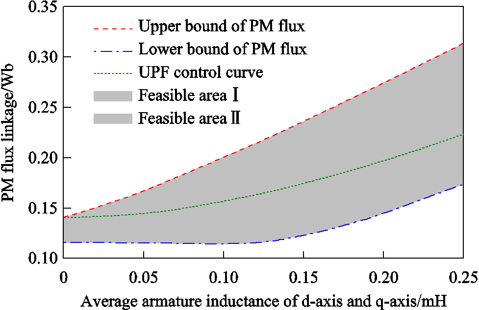
Fig.2 Feasible PM flux linkage and armature inductance at 10kr/min and 335N·m constrained by capacity of power converter
The upper bound of the PM flux linkage (the orange dashed line) and the lower bound (the blue dash-dotted line) show the situations that both voltage and current limit are reached at the rated speed 10kr/min and torque 335N×m. Between the two bounds (i.e., in the colored region) are the conditions that only the voltage limit is reached, with the current lower than the limitation. Furthermore, for the given armature inductances, there is a specific PM flux linkage yf,div with which the armature currents can be minimized when fully utilizing the armature voltage, in other words, the unity-power-factor (UPF) control is realized, hence
 (6)
(6)
By solving Eqns.(1), (4) and (6), the PM flux linkage yf,div can be derived, which is plotted as the green dotted UPF control curve in Fig.2. The afore mentioned colored region can then be divided into two feasible areas, Ⅰ and Ⅱ. Comparing with the current-minimized UPF control curve, the feasible area Ⅰ needs greater amplitude of negative idto weaken the PM flux, whilst the feasible area Ⅱ needs greater amplitude of iqto produce sufficient torque. But, the minimization of current amplitude doesn’t mean the minimization of the total power loss during high-speed operation. When the machine is designed along the dotted line (UPF control at the rated speed and torque), the PM flux is more than those designed in the feasible area Ⅱ, so there will be more iron loss. In general, a larger PM flux is usually avoided due to the following reasons: the PM consumption is more, which increases the difficulty for rotor mechanical design and motor cost; the flux-weakening current is larger, which increases the risk of PM demagnetization and also overvoltage damage in case the power converter is out of control; the iron loss is larger, which harms the efficiency and thermal condition. Therefore, it is recommended to design a machine in the feasible area Ⅱ instead of Ⅰ. Considering the torque requirement and power converter constraints at 10kr/min, the PM flux linkage should be designed between yf,lower and yf,div in Fig.2. Since the limitation should also be satisfied at the maximum-speed operating point (13.5kr/min and 248N·m), there is another set of feasible area Ⅰ and Ⅱ, as shown in Fig.3. Clearly, the intersection of the two feasible areas Ⅱ should be considered, which is colored in green and called “good solution area” in Fig.3.
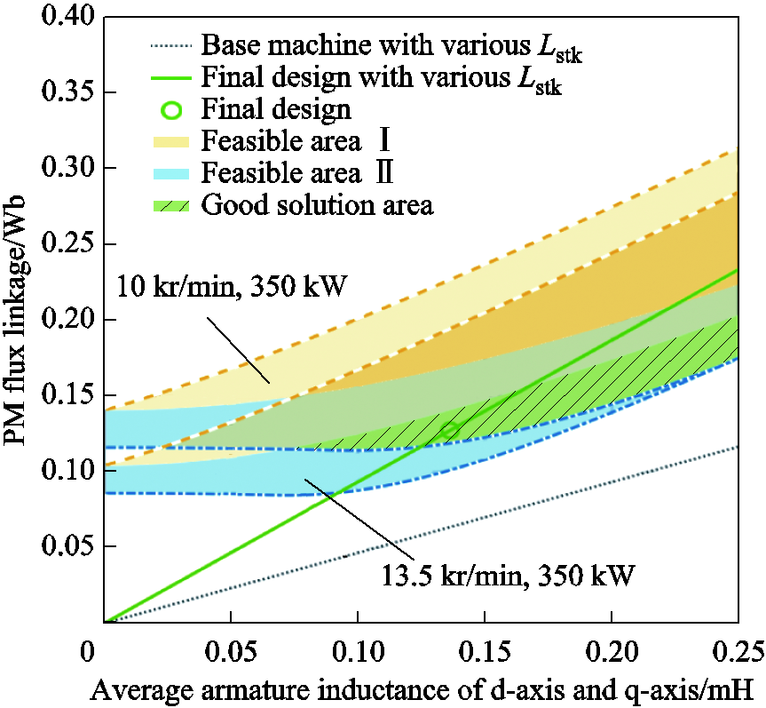
Fig.3 Feasible areas of machine parameters constrained by voltage and current capacity of power converter under two specific operating conditions
When the rotor geometry and material properties have been pre-determined, there are two common ways to adjust the PM flux linkage and armature inductance, one is to adjust the number of turns per coil (Ntpc) and the parallel branches (Npb), the other one is to adjust the stack length (Lstk) of the motor[15]. The PM flux linkage and the armature inductance vary as
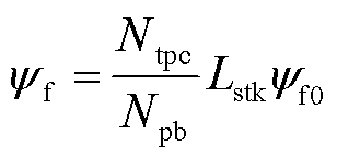 (7)
(7)
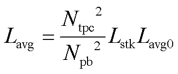 (8)
(8)
where  and Lavg0 are the PM flux linkage and average inductance of Ld and Lq of a base machine. The base machine has one turn per coil, all coils of the same phase in series connection, and unit stack length. A straight line of the point (Lavg0,) of the base machine and the origin can be plotted in Fig.3, i.e., the gray dotted line, and is called “base machine with various Lstk”. This line means that the base machine is modified, by replacing the unit stack length with an actual length Lstk. When designing the actual motor, Ntpc and Npb should be decided first, in order to achieve a reasonable proportional relationship between
 and Lavg. In order to achieve a smaller armature inductance at the same, either smaller Ntpc or greater Npb should be applied. For the studied motor, by fully considering the motor size, voltage, current and many other constraints, as well as the manufacturing easiness, Ntpc is set as 1 and Npb is set as 2. Thus, by changing the stack length Lstk, the relationship between yf and Lavg is plotted in Fig.3 as the green solid line, and called “actual machine with various Lstk”. Obviously, this line should cross the (green) “good solution area” in Fig.3, otherwise, Ntpc and Npb should be re-decided. Furthermore, the stack length is selected as 300mm, to achieve the work point of the green circle (final design) within the green area (good solution area), see Fig.3, with the PM flux linkage being 0.1274Wb, and the average armature inductance being 0.136 3mH. Hence, Ld and Lq are 0.120 7mH and 0.151 9mH, respectively.
The IPM rotor configuration is shown in Fig.4. Each pole has several segments of magnets, so that each segment is sufficiently small to be held by the ribs of rotor core laminations. The conventional shape of the magnets for an IPM rotor is rectangular, chamfered with round corners, as shown in Fig.4a. Since the magnets are manufactured with wire cutting, their shapes are actually flexible in the design stage. To achieve better magnetic and mechanical performances, the shape of the magnets is designed as Fig.4b. The magnets are of tile-shape with round corners, which can reinforce the rotor PM field as well as the rotor strength.

Fig.4 IPM rotor structure with different magnet shapes
When analyzing the rotor stress, 1.2 times over speed is usually considered in industry practice, and, under this over speed the maximum stress should be lower than the material yield strength. In another way, the rotor stress is calculated at the highest operation speed, whilst the maximum stress must be lower than the yield strength with a safety factor of 1.414 or even slightly larger. In this paper, the second way is used, and the safety is chosen as 1.5. The yield strength of the lamination material (35WW300) is 392MPa, therefore, the maximum stress at the highest speed (13.5kr/min) must not exceed 261MPa.
In order to maintain similar electromagnetic performances when optimizing the rotor structure, the radial thickness and the outer radius of the magnets are pre-fixed, as 6mm and 112mm, respectively. In this case, the three dominant factors influencing the rotor stress are shown in Fig.5: the number of magnet segments along the rotor circumference Nmag (note, Nmag = 24 in Fig.4 as an example), the width of the ribs Wrib, and the width of the rotor edge Wedge. Note, the rib and rotor edge are also called radial and circumferential bridges. It should be noted that when comparing rotors with different segmentation of magnets, the product of Wrib and Nmag is set as a constant to ensure similar electromagnetic performances, such as similar flux leakage of the magnets. For example, 24 segments with ribs of 2mm is comparable with 32 segments with ribs of 1.5mm, both having the total rib width of 48mm.
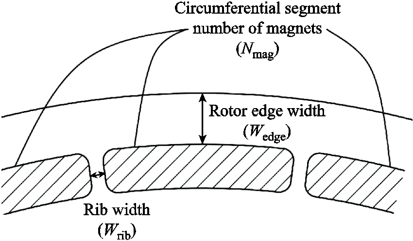
Fig.5 Parameters of rotor stress optimization
The number of magnet segments Nmag should be chosen as a multiple of the pole number, such as 24, 28, 32, and 36. It has been mentioned in literature that increasing the number of circumferential magnet segments can reduce the maximum rotor stress[25], which is also validated in this machine. In order to ensure the universality of the conclusion, comparisons with FEA have been carried out in two aspects: rotors with the same rotor edge width (3mm) but different total rib width (see Fig.6a); rotors with the same total rib width (48mm) but different rotor edge width (see Fig.6b). It is proved that evenly dividing the magnets into more segments can reduce the rotor maximum stress. From Fig.6a it can be observed that the influence of the number of magnet segments is much greater than that of the total rib width. Simply increasing the rib width within a reasonable range has a little improvement on the rotor stress situation, but, keeping the total rib width unchanged but increasing the number of magnet segments can dramatically reduce the rotor stress. On the other hand, with the same total rib width of 48mm, Fig.6b shows the influence of the rotor edge width. For the rotors with a thin edge (3mm and 5mm), increasing the number of magnet segments is also helpful. However, for the rotors with a relative thick edge (such as 7mm), having more segments does not help much in rotor stress reduction.
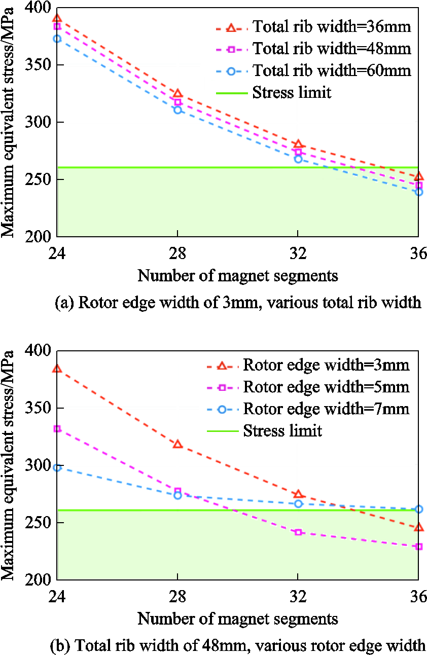
Fig.6 Maximum rotor stress under different number of magnet segments
From the analysis in Fig.6, the number of magnet segments is chosen as 32 as a possible solution, so that the influence of rotor edge width and rib width on the maximum stress can be investigated in this section. The finite element analysis (FEA) investigation results are shown in Fig.7. From Fig.7a it can be observed that at each rib width, there is an optimum rotor edge width which can minimize the rotor stress. If the ribs are thicker, the optimum rotor edge width is also thicker, and the achievable minimized rotor stress can be smaller, too. The rotor stress can be divided into two parts, the radial component (see Fig.7b) and the tangential component (see Fig.7c). The maximum radial stress appears at the rib, which is tensile as a result of the centrifugal force of the rotor edge and the magnets. Therefore, as the rotor edge expands, the radial stress on the ribs becomes larger, and, when the ribs are wider, this tensile stress can be reduced. Furthermore, the rotor edge can be considered as a retaining sleeve, which suffers from large tensile stress when its thickness is not enough to hold the magnets.
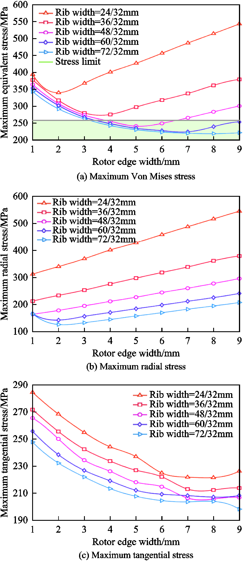
Fig.7 Maximum rotor stress and its components under different rotor edge width and total rib width (all with 32 circumferential segments of magnets)
As a result, the maximum tangential stress appears at the outer corners of the magnet windows. When the rib width is too small compared with the rotor edge width, the radial stress at the ribs leads to the maximum rotor stress, while when the rotor edge width is too small compared with the rib width, the tangential stress at the corners dominates. Therefore, the rib width and the rotor edge width should be compatible so as to achieve a balance between the two stress components and to minimize the overall rotor stress.
As shown in Fig.7a, there are many feasible solutions with 32 magnet segments, and the results are replotted into contour in Fig.8a. Moreover, the situation of the rotor with 28 magnet segments is shown in Fig.8b, comparatively. Similar contour figures for the other numbers of magnet segments are also made, although are not shown here. The deepest blue areas represent the combinations of total rib width and rotor edge width that can restrain the rotor stress within the limitation (261MPa). Meanwhile, the electromagnetic performance must be considered, too, thus, both Wedge and Wrib should be minimized to reduce the PM flux leakage through the rotor core.
Under comprehensive consideration, the rotor structure with 32 magnet segments is eventually chosen, and the total rib width is set as 48mm, i.e., Wrib = 1.5mm, and the rotor edge width Wedge is 5mm. This result is marked in Fig.8a, showing a reasonable tolerance to the stress limit.
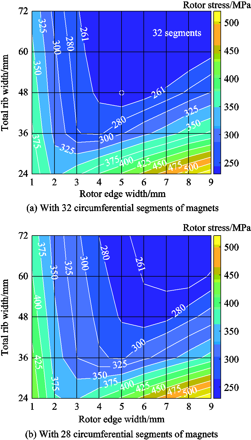
Fig.8 Maximum rotor stress with different rotor edge width and total rib width
The inner diameter of the rotor core (i.e., the shaft diameter) is fixed as 95mm, according to the output torque level, and the primary rotor is shown in Fig.9a. Then, some windows are employed on the rotor laminations, so as to reduce the rotor weight. In order to maintain the flux path of a 4-pole rotor, these windows should not be too close to the magnets, leaving adequate yoke thickness between them. The distance between these windows is optimized, and the window corners are properly chamfered, in order to achieve a balance between the radial and tangential stress. As a result, the maximum stress barely increases after adding these windows, as shown in Fig.9b. In light of rotor lamination stacking and fixture, 8 bolt holes are evenly arranged between the weight-reducing windows.
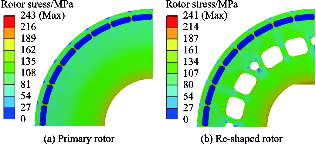
Fig.9 Rotor stress distribution at 13.5kr/min
For the large-power high-speed interior PMSM, it is not easy to install the rotor core onto the shaft with the heat-shrinking process. One reason is that, although the lamination dimensions can be precise, after manual stacking, the core dimensions such as the inner diameter are less precise, therefore, it is difficult to ensure an appropriate tolerance between the core inner bore and the shaft. The other reason is that the heat-shrinking process may cause deformation of the magnet windows on the rotor core, either making it very difficult to insert the magnets, or loading a severe stress on the magnets if the magnets have already been inserted and even damaging the magnets. Therefore, transition fit can be used between the core inner bore and the shaft. Then a key bar is usually needed to fix the rotor core. However, in the studied motor, there is a severe stress at the corner of the key bar slot of the lamination. To avoid the key bar structure, it is then proposed to milling the shaft with two flats, and the core inner bore is re-shaped accordingly, as shown in Fig.9b. The stress is satisfactory, with 241MPa as the maximum, appearing in the ribs.
Rotor resonance is also a crucial issue in high-speed machines, which can cause violent vibration and even damage to the machine structure[26]. For the sake of safety operation, critical speeds of the rotor must be calculated in advance, and to be strictly avoided in the motor operation. Rotor dynamics analysis is also carried out with the finite element method (FEM), where the rotor is supported by two bearings with the radial stiffness of 1MN/m. The Young’s modulus of the rotor stack is set as 200GPa considering the laminated structure. Rotor modal mainly includes lateral (or translation) modes, conical (or swing) modes, bending modes, and rotational modes[27]. Although the rigid modes (lateral and conical modes) always appear at low frequency, they rarely influence the practical operation[14,18,25]. Therefore, usually they are not considered for the critical frequencies. In most cases, it is the bending and rotational modes (see Fig.10) that determine the critical speeds of the rotor. The gyroscopiceffect is also taken into account, so that each type of rotor modal has two adjacent critical frequencies, a backward one and a forward one.
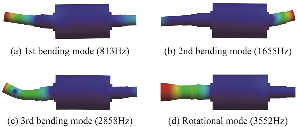
Fig.10 Rotor modal analysis results
The Campbell diagram of the investigated rotor is depicted in Fig.11, which takes the gyroscopic effect at various speeds into account. Although the operation line intersects with the lines of rigid modes at low frequencies, they are trivial for practical operation. Besides, the bending mode lines are far above the operating line, therefore, no critical speed will be reached during the full speed range operation. However, it must be noted that there are high order force ripples, the frequencies of which are multiple of the rotation frequency, therefore, further analysis is required for the final design confirmation.
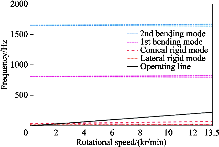
Fig.11 Campbell diagram considering gyroscopic effect
High-speed machines enjoy the merit of high power density, but also suffer from the problem of high loss density. Hence, thermal design is particularly required. Winding impregnation or encapsulation can be employed, whilst liquid cooling or forced air cooling can be rather effective[28], hence, single- or even double-phase fluid dynamics computation is needed, coupling with thermal analysis. Furthermore, some measures to enhance the fluid dynamics such as introducing extra air channels in the stator core will also affect the motor electromagnetic performance.
In this design case, water cooling with a Z-shaped channel is applied (see Fig.12). The power loss of the electrical machine reaches the maximum value at 13.5kr/min and 350kW, therefore, the thermal validation is carried out under this operating condition. Iron and magnet losses are mapped from the 2-dimensional electromagnetic model onto the 3-dimensional thermal model, and copper loss is evenly loaded both on the effective part and on the end windings according to the loss density. A rotating surface is applied on the rotor to represent its rotation, and the air in the air gap is rotating in the same direction as the rotor. Energy exchange due to ambient convection is neglected, hence all the power losses are assumed to be taken away by the cooling liquid. The inlet velocity of the cooling water is 10L/min, and the inlet temperature is 29.8℃(303K). With computational fluid dynamics (CFD) simulation, the velocity distribution of the cooling fluid and its temperature distribution in the channel are calculated, as shown in Fig.13. The temperature distribution of the motor is depicted in Fig.14. The highest temperature which is 93.4℃ appears at the winding end, due to the totally enclosed housing. While the highest rotor temperature is 89.4℃ at the rotor surface and inside the magnets. Considering the PM grade being N42UH, or working temperature being up to 180℃, this thermal condition is adequate for long term safe operation. It is noted that currently in most industry products of large-power high-speed PMSM, SmCo magnets are used due to their low temperature coefficient. However, in this study case, it can be seen that the PM temperature can be well controlled with proper design, therefore, the NdFeB magnets which are cheaper and have higher energy than the SmCo magnets can be employed.
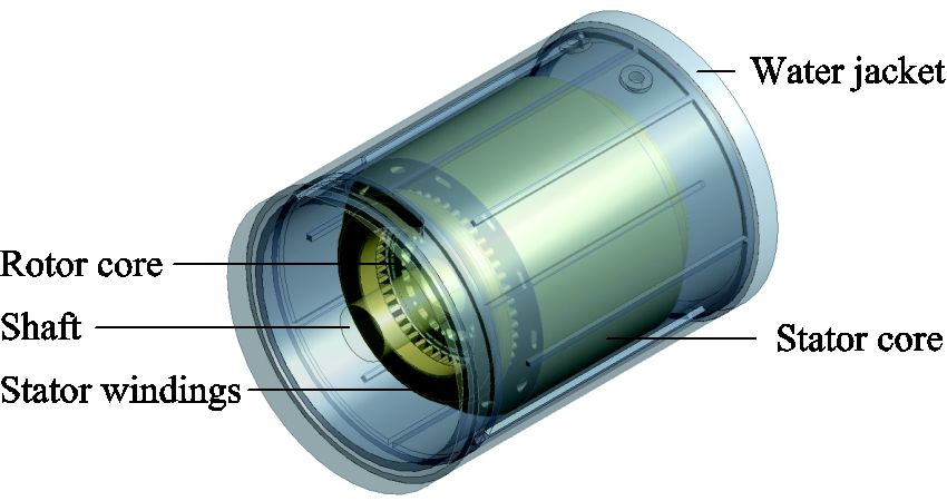
Fig.12 Thermal analysis model

Fig.13 Computational fluid dynamics results at 13.5kr/min and 350kW
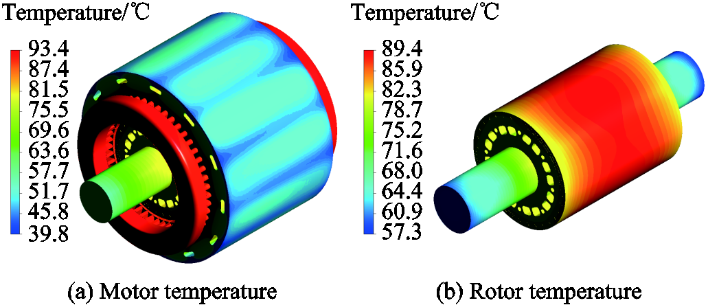
Fig.14 Temperature distribution at 13.5kr/min and 350kW
Clearly, various physical fields are deeply coupled in the high-speed large-power motors, thus, compromises must be made. Multi-physics analysis is not only essential, but also need to be iterated, so as to achieve an overall satisfactory performance[17]. A comprehensive design method for the high-speed PMSM is presented, including the electromagnetic, mechanical (stress and rotor dynamics), fluid and thermal aspects, as well as the constraints from the power converter, as shown in Fig.15.
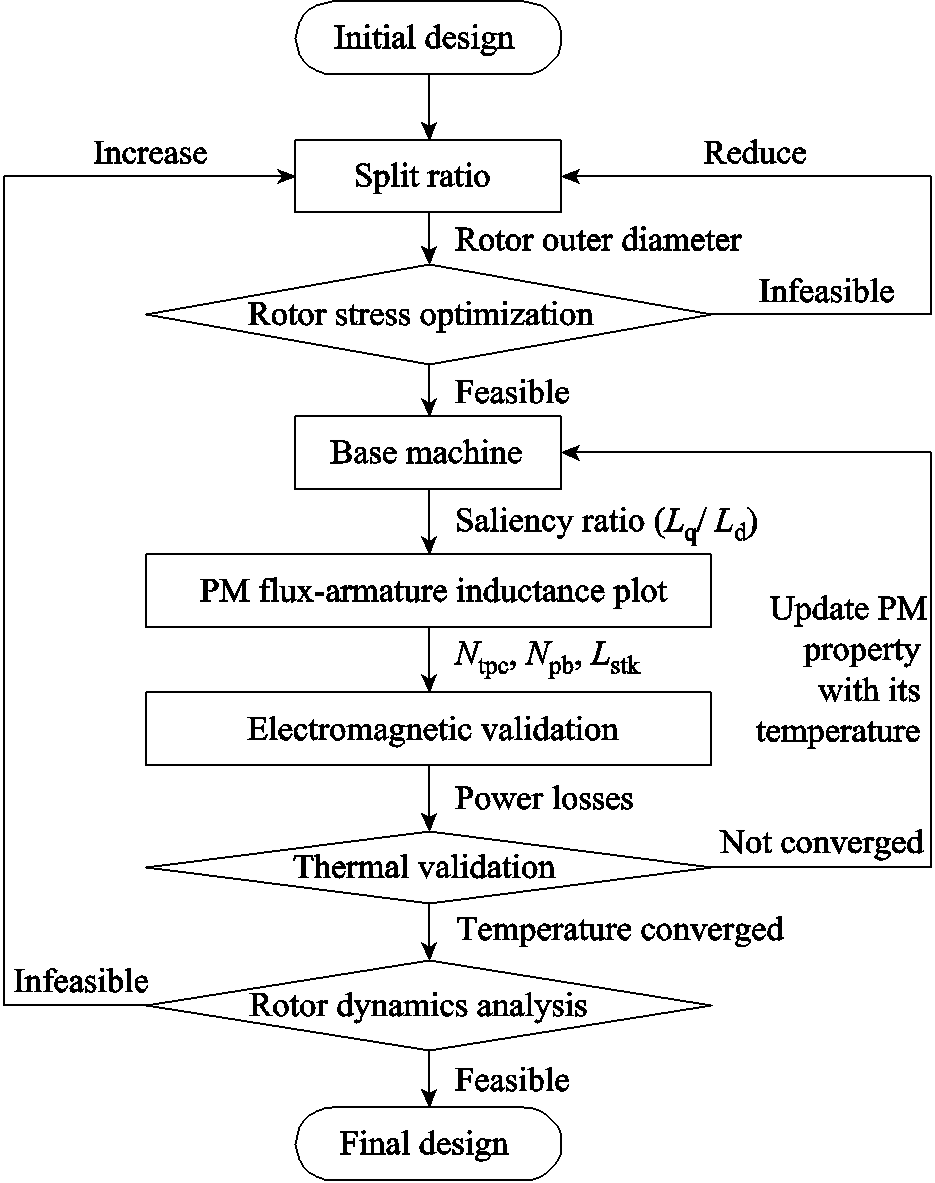
Fig.15 Comprehensive design procedure for high-speed PMSM
First, an initial design is put forward, including the potential frame size, pole number, slot number, air gap width, and split ratio. Then, the rotor structure is optimized to reduce the stress. If it is impossible to design an appropriate rotor structure at this rotor diameter, split ratio should be reduced. After deciding the rotor structure, the base machine with unit stack length and series-connected single-turn coils is evaluated at 120℃as a reference. The saliency ratio (Lq/Ld) is calculated with FEA, and the  plot can be derived considering the constraints by the power converter. The numbers of turns per coil and parallel branches, and the stack length, can then be decided according to the feasible area in the plot, and the electromagnetic performance is validated. Power losses are derived from the electromagnetic analysis, and are mapped onto the thermal model as heat sources. CFD is employed to calculate the cooling effect of the water jacket, and the thermal performance is obtained. If the calculated PM temperature (TPM) is higher than 120℃, the property of the magnets was over-valued in the previous electromagnetic analysis, hence iterations should be carried out between the electromagnetic and thermal validation to seek the real operating point[29]. Of course, the temperature of other parts of the motor should be checked, too, to avoid any over-temperature. After all, rotor dynamics is analyzed, considering the rotor and the bearing system altogether.
After iterative analysis and optimization, the studied 350kW 10kr/min PMSM has been designed. Particular considerations have been made for the rotor design, as most physical fields have significant effects on it. The design parameters, as well as the mechanical and thermal performance are shown in Tab.1, all satisfying the design targets.
Tab.1 Design parameters and performance of studied high-speed PMSM
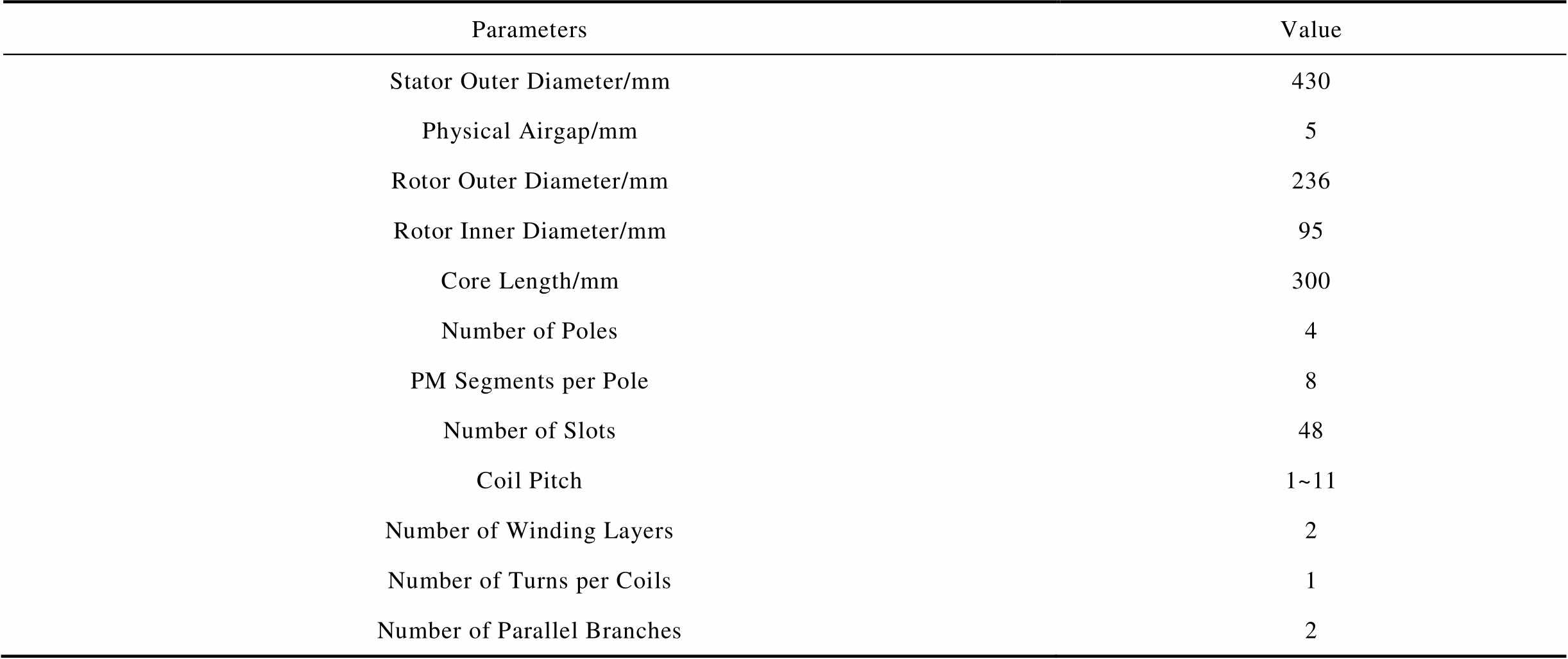
ParametersValue Stator Outer Diameter/mm430 Physical Airgap/mm5 Rotor Outer Diameter/mm236 Rotor Inner Diameter/mm95 Core Length/mm300 Number of Poles4 PM Segments per Pole8 Number of Slots48 Coil Pitch1~11 Number of Winding Layers2 Number of Turns per Coils1 Number of Parallel Branches2
(续)
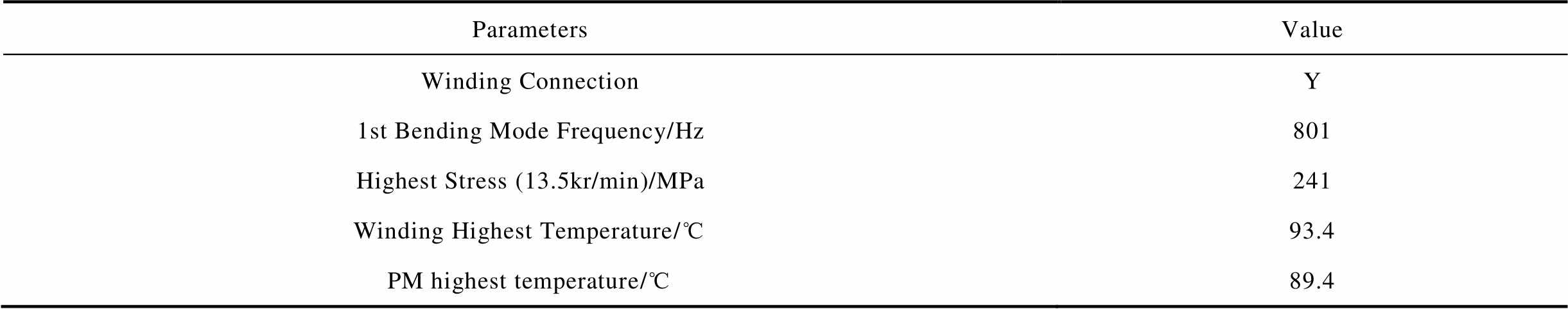
ParametersValue Winding ConnectionY 1st Bending Mode Frequency/Hz801 Highest Stress (13.5kr/min)/MPa241 Winding Highest Temperature/℃93.4 PM highest temperature/℃89.4
Flux-weakening control is surely needed for the highest speed operation (350kW 13.5kr/min). Analysis similar to Fig.1 is made for the rated operation (350kW 10kr/min) and even lower-speed constant torque operation, and it is found that a proper negative id is helpful to increase the machine output. The final design is re-investigated with electromagnetic FEA, so that the performance with proper id and iq can be obtained, as shown in Tab.2.This table is input to the power converter controller as a look-up table, so as to achieve proper vector control of the PMSM.
Tab.2 Armature currents, voltage and electromagnetic performance of studied high-speed PMSM
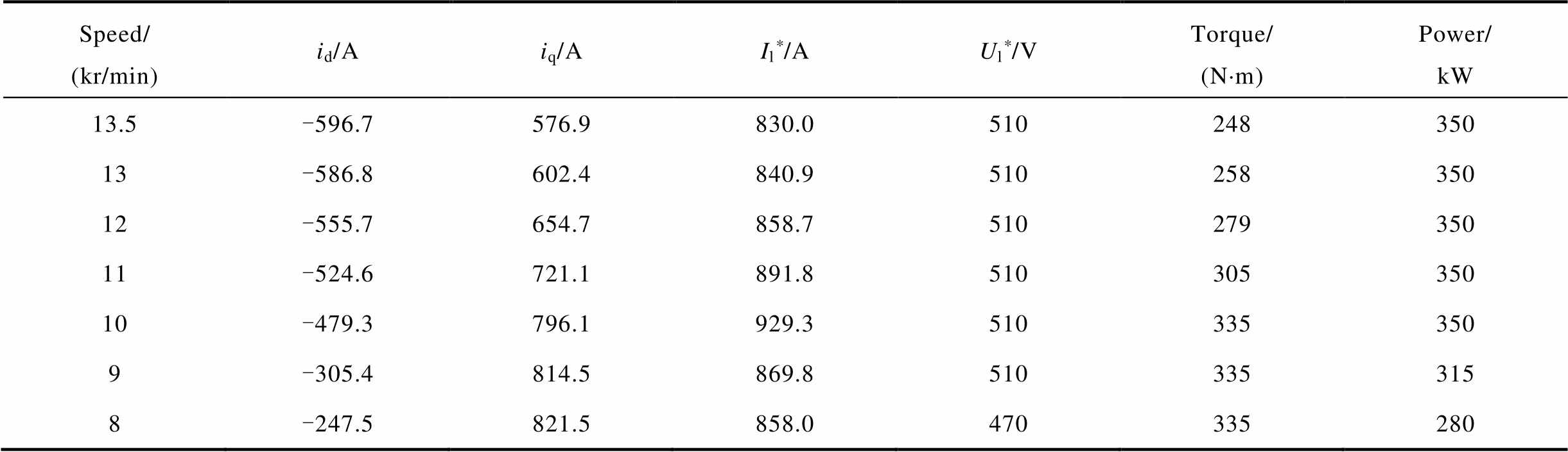
Speed/(kr/min)id/Aiq/AIl*/AUl*/VTorque/(N×m)Power/kW 13.5-596.7576.9830.0510248350 13-586.8602.4840.9510258350 12-555.7654.7858.7510279350 11-524.6721.1891.8510305350 10-479.3796.1929.3510335350 9-305.4814.5869.8510335315 8-247.5821.5858.0470335280
* Il is amplitude of the sinusoidal line current, Ul is the amplitude of the line-line voltage fundamental component.
The motor prototype was fabricated, its rotor and stator of the prototype are shown in Fig.16a and Fig.16b. Also, the motor housing with water cooling jacket is designed. The whole machine on the test bench is shown in Fig.16c. As can be predicted with electromagnetic FEA, harmonics exist in the back EMF of each phase, however, the 0-sequence harmonics (i.e., the 3rd and all other multi-triple order harmonics) do not exist in the line-line back EMF since the windings are Y-connected.
Therefore, the back EMF of each phase subtracted by the 0-sequence harmonics was directly measured at 1kr/min at room temperature, as shown in Fig.17a. This EMF (in RMS value) coefficient is thus obtained as 19.8V/(kr/min), and the THD is low, in other words, the 5th, 7th and other non-0-sequence harmonics are low. On the other hand, the phase back EMF subtracted by the 0-sequence harmonics was calculated with FEA at the rated speed 10kr/min and room temperature, as shown in Fig.17b, with the EMF coefficient being 21.0V/(kr/min) and the THD being 1.3%. There is a small error of EMF between the test and calculation results. As can be seen from Fig.16a, two stainless steel endcaps are used on the rotor. The endcaps become slightly magnetic after lathe-machining, and thus cause extra 3D-effect leakage of the PM flux and consequently the EMF error. On the other hand, in this machine, the rotor saliency is low, hence, the electromagnetic torque is dominated by the PM mutual torque. The motor output torque was not measured in the test, since it was not realistic to install a torque meter for such a large-power high-speed system. However, as long as the EMF coefficient is predictable, the torque is predictable, too, especially in this studied machine the core field is designed at a low level hence there is little core saturation. The PM temperature could not be measured, either. After the test the PMs were not demagnetized, hence, over temperature did not occur. No rotor resonance occurred, showing the 1st bending mode frequency is beyond the operation speed range. After the test the motor was disassembled, and no rotor deformation was observed, thus, it is safe against the centrifugal stress.
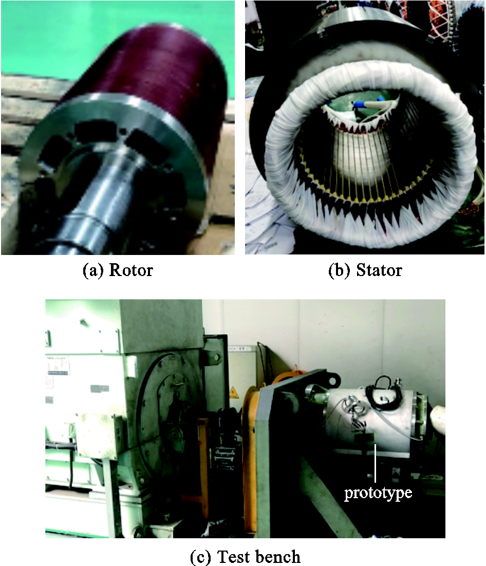
Fig.16 Motor prototype
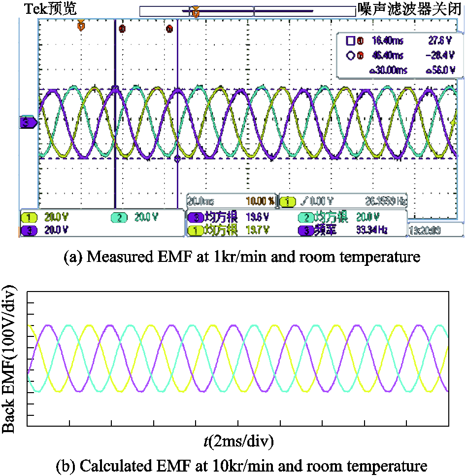
Fig.17 Phase EMF subtracted by 0-sequence harmonics
Clearly, machine fabrication is very important, since any imperfectness in, for example, rotor balancing and winding assembling may cause eventual failure of the products. In actual fact, the prototype suffered from the rotor unbalancing which could not be foreseen with analysis and design, hence, its vibration was severe, limiting its long-term operation.
In this paper, the comprehensive analysis and design procedure of a high-speed large-power PMSM is presented, taking the multi-physics fields coupling and power converter constraints in consideration. First, the pattern of the rotor is chosen and the rotor dimensions are optimized to meet the stress limitations. Influence of the magnet circumferential segmentation and geometric parameters on the rotor maximum stress is investigated. Then, the electromagnetic scheme is accomplished with the stress-optimal rotor adopted. The voltage and current constraints by the power converter are converted into the constraints on the PM flux linkage and armature inductance, so that it can be taken into account during the electromagnetic design. The armature winding parameters and the stack length are decided according to the relationship between the PM flux linkage and armature inductance. Afterwards, thermal analysis and validation are carried out under the greatest power loss and the proposed water-cooling condition. Finally, the rotor critical frequencies are derived with FEM, which is proved to be much above the working frequencies, thus qualifying safe operation. Iteration of these design proceeds, until all performance-associated physical fields are satisfied. A prototype motor with 13.5kr/min and 350kW validates the effectiveness of this procedure of multi-physics analysis and design.
Reference
[1] Qin Xuefei, Shen Jianxin. Multi-physics design of high-speed large-power permanent magnet synchronous motor[C]//Fifteenth International Conference on Ecological Vehicles and Renewable Energies (EVER), Monte-Carlo, Monaco, 2020: 1-5.
[2] Gerada D, Mebarki A, Brown N L, et al. High-speed electrical machines: technologies, trends, and developments[J]. IEEE Transactions on Industrial Electronics, 2014, 61(6): 2946-2959.
[3] Ma J, Zhu Z Q. Optimal split ratio in small high speed PM machines considering both stator and rotor loss limitations[J]. CES Transactions on Electrical Machines and Systems, 2019, 3(1): 3-11.
[4] Cheng Xin, Xu Wei, Du Guanghui, et al. Novel rotors with low eddy current loss for high speed permanent magnet machines[J]. CES Transactions on Electrical Machines and Systems, 2019, 3(2): 187-194.
[5] Wang Xiaolin, Liu Sihao, Gu Cong. A rotor position error compensation algorithm for high-speed permanent magnet motor based on phase-locked loop with adaptive reference[J]. Transactions of China Electrotechnical Society, 2021, 36(20): 4308-4317.
[6] Shen Jianxin, Qin Xuefei, Wang Yunchong. High-speed permanent magnet electrical machines- applications, key issues and challenges[J]. CES Transactions on Electrical Machines and Systems, 2018, 2(1): 23-33.
[7] Tenconi A, Vaschetto S, Vigliani A. Electrical machines for high-speed applications: design considerations and tradeoffs[J]. IEEE Transactions on Industrial Electronics, 2014, 61(6): 3022-3029.
[8] Lin Hao, Geng Haipeng, Yu Lie, et al. Electromechanical analysis and experiment for a high-speed permanent magnet synchronous compressor supported by elastic foil bearing[C]//IEEE/ASME International Conference on Advanced Intelligent Mechatronics (AIM), Hong Kong, China, 2019: 1080-1085.
[9] Dubas F, Espanet C, Miraoui A. Design of a high-speed permanent magnet motor for the drive of a fuel cell air-compressor[C]//IEEE Vehicle Power and Propulsion Conference (VPPC), Chicago, USA, 2005: 603-610.
[10] Arslan S, Iskender I. Design aspects of a 26500-rpm: 2-kW high-speed permanent magnet synchronous generator for turbomachinery systems[C]//8th International Conference on Electronics, Computers and Artificial Intelligence (ECAI), Ploiesti, Romania, 2016: 1-6.
[11] Kim S, Seok J K. Comprehensive PM motor controller design for electrically assisted turbo-charger systems[C]// IEEE Energy Conversion Congress and Exposition (ECCE), Denver, USA, 2013: 860-866.
[12] Wheeler N. Voltage regulation application of a kinetic energy storage system[C]//Second International Conference on Power Electronics, Machines and Drives (PEMD), Edinburgh, UK, 2004: 605-608.
[13] Fang Haiyang, Li Dawei, Qu Ronghai. Rotor design and eddy-current loss suppression for high-speed machines with a solid-PM rotor[J]. IEEE Transactions on Industry Applications, 2019, 55(1): 448-457.
[14] Fang Haiyang, Qu Ronghai, Li Jian, et al. Rotor design for high-speed high-power permanent-magnet synchronous machines[J]. IEEE Transactions on Industry Applications, 2017, 53(4): 3411-3419.
[15] Fernando W, Arumugam P, Gerada C. Volt-ampere constrains and its influence on inductance limits in high speed PM machine design[C]//IET International Conference on Power Electronics, Machines and Drives (PEMD), Glasgow, UK, 2016: 1-7.
[16] Zhao Weiduo, Wang Xuejiao, Gerada C, et al. Multi-physics and multi-objective optimization of a high speed PMSM for high performance applications[J]. IEEE Transactions on Magnetics, 2018, 54(11): 8106405(1-5).
[17] Wang Tianyu, Du Guanghui, Yu Zhong, et al. Design and develop of a MW direct drive high-speed permanent-magnet machine for compression[C]// International Conference on Electrical Machines and Systems (ICEMS), Busan, Korea, 2013: 892-895.
[18] Huang Ziyuan, Fang Jiancheng. Multiphysics design and optimization of high-speed permanent-magnet electrical machines for air blower applications[J]. IEEE Transactions on Industrial Electronics, 2016, 63(5): 2766-2774.
[19] Zhang Fengge, Du Guanghui, Wang Tianyu, et al. Rotor retaining sleeve design for a 1.12-MW high-speed PM machine[J]. IEEE Transactions on Industry Applications, 2015, 51(5): 3675-3685.
[20] Bernard N, Missoum R, Dang L, et al. Design methodology for high-speed permanent magnet synchronous machines[J]. IEEE Transactions on Energy Conversions, 2016, 31(2): 477-485.
[21] Wang Tianyu, Wang Zerun, Bai Bin, et al. Sensitivity analysis of rotor strength of megawatt high speed permanent magnet motor[J]. Transactions of China Electrotechnical Society, 2021, 36(S1): 107-114.
[22] Han Ting, Wang Yunchong, Shen Jianxin. Analysis and experiment method of influence of retaining sleeve structures and materials on rotor eddy current loss in high-speed PM motors[J]. IEEE Transactions on Industry Applications, 2020, 56(5): 4889-4895.
[23] Shen Jianxin, Han Ting, Yao Lei, et al. Is higher resistivity of magnet beneficial to reduce rotor eddy current loss in high-speed permanent magnets AC machines?[J]. Transactions of China Electrotechnical Society, 2020, 35(9): 2074-2078.
[24] Chu Guoyu, Dutta R, Rahman M F, et al. Analytical calculation of maximum mechanical stress on the rotor of interior permanent-magnet synchronous machines[J]. IEEE Transactions on Industry Applications, 2020, 56(2): 1321-1331.
[25] Riemer B, Lebmann M, Hameyer K. Rotor design of a highspeed permanent magnet synchronous machine rating 100 000rpm at 10kW[C]// IEEE Energy Conversion Congress and Exposition (ECCE), Atlanta, USA, 2010: 3978-3985.
[26] Ede J D, Zhu Z Q, Howe D. Rotor resonances of high-speed permanent-magnet brushless machines[J]. IEEE Transactions on Industry Applications, 2002, 38(6): 1542-1548.
[27] Xing Zezhi, Wang Xiuhe. Critical speed calculation and modal analysis of rotor for high-speed machine[C]// IEEE Transportation Electrification Conference and Expo, Asia-Pacific (ITEC), Harbin, China, 2017: 1258-1263.
[28] Dong Baotian, Wang Kun, Han Bangcheng, et al. Thermal analysis and experimental validation of a 30kW 60000r/min high-speed permanent magnet motor with magnetic bearings[J]. IEEE Access, 2019, 7: 92184-92192.
[29] Wang Tianyu, Zhang Yue, Wen Fuqiang, et al. Coupling calculation and analysis of three-dimensional temperature and fluid field for high-power high-speed permanent magnet machine[J]. IET Electric Power Applications, 2019, 13(6): 820-825.
摘要 高速电机中多物理场是强耦合的,其影响是甚至相互矛盾的。因此,高速电机的设计受到多物理场的强制约。此外,变流器的电压和电流都受限,由此也制约了高速电机的设计。当电机功率较大时,所有这些约束变得更加显著,因此较难获得一个很好的优化设计方案。该文以一台350kW、13.5kr/min的大功率高速内置式永磁同步电机作为案例,阐述其设计方法与优化过程。针对不同工况,研究电机永磁磁链与绕组电感的匹配设计,以确保变流器的电压和电流限制均得到满足。之后,通过有限元的手段研究相关的电机设计要点,特别是考虑电磁特性、机械应力和动力学特性的转子拓扑结构;也通过计算流体动力学(CFD)手段研究电机的热性能。由此可实现完整的高速电机多物理场设计。
关键词:高速永磁同步电机 多物理场设计 变流器约束 转子拓扑 热性能
中图分类号:TM355
Received October 8, 2021;
Revised February 10, 2022.
DOI:10.19595/j.cnki.1000-6753.tces.211568
Notes Brief
Qin Xuefei female, born in 1996, PhD student. Her main research interests include design of high-speed permanent magnet synchronous machines.E-mail: xuefeiqin@zju.edu.cn
Shen Jianxin male, born in 1969, professor. His main research interests include design, control and applications of PM machines, SynRM, high speed machines, and high efficiency motor drives.E-mail: J_X_Shen@zju.edu.cn (Corresponding author)
This work was supported by the Natural Science Foundation of China under grants of 51837010 and 51690182, and by the TECO-20190415 Research Fund.
(编辑 郭丽军)