 和
和 为由逆变器输出的高频交流电压和电流,L1和L2为谐振电感,LP和LS为原边线圈自感和副边线圈自感,M为线圈互感,L3为辅助电感,CP、C1和C2为补偿电容,RL为等效负载,
 、
、 、
、 和
和 分别为原边线圈电流、副边线圈电流、副边谐振腔输出电压和输出电流。
摘要 为了解决无线充电中恒流充电模式向恒压充电模式切换过程复杂、控制电路设计难度系数高的问题,该文基于双边LCL拓扑设计一种变补偿参数的磁耦合谐振式无线充电系统,该系统仅需投切副边额外增加的电感即可完成恒流充电向恒压充电的平滑转换,省去原、副边之间的通信,降低控制电路设计的复杂性,提高无线充电系统整体的效率和稳定性。该文首先对双边LCL变补偿拓扑进行理论分析,推导得到系统原边恒流、副边恒流恒压的条件;然后通过对系统恒流向恒压切换过程进行瞬态分析,实现切换的平滑过渡;最后对所设计的无线充电系统进行仿真与实验验证。结果表明:该系统可以实现恒流向恒压的平滑切换,且在恒流3A和恒压60V的充电条件下充电电流偏差和充电电压偏差较低,分别为1.65%和1.8%,均满足电池充电要求;并在恒压充电模式下,系统副边谐振网络输出电流波形得到明显改善,波形畸变率由15.43%降到1.24%。
关键词:无线充电 双边LCL 恒流 恒压
传统插拔式充电方式存在充电不方便、拔插出现火花及触电隐患等问题,在一定程度上限制了智能产品的升级换代,越来越不能满足当今用户的需求。而无线充电技术具有安全、便捷、可靠的优 点[1],已在智能手机[2-3]、家用电器[4]、智能飞行 器[5]、医疗机械[6-8]、电动汽车等领域得到广泛应 用[9-11]。无线充电系统在对电池进行充电过程中需先保持恒流(Constant Current, CC)充电,在到达一定电压后再保持恒压(Constant Voltage, CV)充电,直到充电结束[12-14]。
为实现无线充电过程中CC模式和CV模式,相关研究人员提出了几种不同的控制策略。通过在原边或副边添加额外DC电路实现CC和CV输出[15-18],这种方法不仅会增加系统损耗,降低系统效率,还会增加元器件数量,使系统成本大大增加。通过原、副边实时通信对逆变器进行移相控制,调节逆变器基波电压以满足后级充电系统所需电流、电压[19-21]。这种调节方式在轻载工况时,系统很难实现零电压开关,会降低充电效率。通过调频控制实现充电系统CC和CV模式[22-24],这种方法不仅在变负载工况下存在频率分叉现象[25-26],此外,还需要原、副边高速通信,加大了系统控制难度。针对以上充电切换方式存在的不足,国内外研究人员又通过研究补偿拓扑实现CC和CV输出。文献[27-28]对串联-串联(Series-Series, SS)和LCL补偿拓扑进行改进,通过对原边补偿电路分析,在原边增加电容和开关支路实现恒流恒压充电模式切换,该方法仍然需要原、副边进行通信,依然不能简化系统。文献[29]设计一种LCL-LC/LCL型补偿拓扑实现恒流恒压模式的切换,该拓扑省去了原、副边通信,需要在副边使用3个开关管,开关管的复杂控制给系统的稳定性带来了一定的影响。文献[30]提出了一种LCC-S补偿的混合拓扑结构,仅需一个开关器件就可以实现CC和CV的充电,简化了系统结构,降低了控制成本。但是两种充电模式需要两种不同频率控制,会给系统的稳定性带来影响。因此,设计一种结构简单、能省去原、副边通信的补偿拓扑,实现恒流、恒压充电模式平滑切换,对无线充电系统的稳定性和效率提升具有重要意义。
本文基于双边LCL电路补偿结构提出了一种在副边电容支路额外串联一组电容和电感的新型变参数补偿结构,只需要通过投切电感来改变次级补偿的参数即可完成恒流向恒压的切换。该补偿结构只在副边增加一个开关器件,省去了原、副边通信,简化了系统结构,降低了控制难度;并且在恒压模式时利用辅助电感和额外补偿电容组成LC滤波器滤除副边谐振腔的高次谐波,可以有效地改善无线充电系统在恒压模式时输出电流的波形,减少系统损耗,提高无线充电系统整体的效率和稳定性。最后,根据所提出的拓扑结构,搭建了一套实验样机,验证了所提方法的正确性。
本文所提出的双边LCL变参数补偿电路如图1所示。图中,和为由逆变器输出的高频交流电压和电流,L1和L2为谐振电感,LP和LS为原边线圈自感和副边线圈自感,M为线圈互感,L3为辅助电感,CP、C1和C2为补偿电容,RL为等效负载,、、和分别为原边线圈电流、副边线圈电流、副边谐振腔输出电压和输出电流。
副边等效阻抗Zeq反射到原边得到原边等效电路如图2所示, 为等效阻抗Zeq两端的电压。
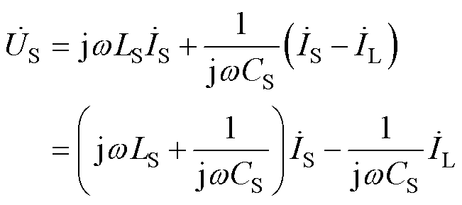
假设系统工作角频率为w,对图2谐振电路列写KVL方程为
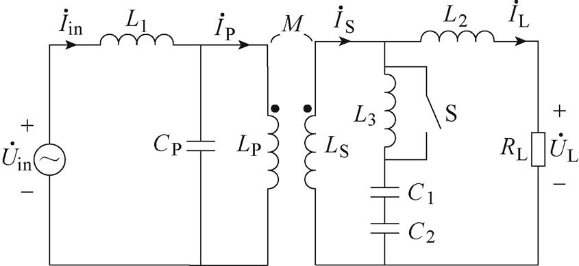
图1 双边LCL变参数补偿谐振电路
Fig.1 Bilateral LCL variable compensation resonant circuit
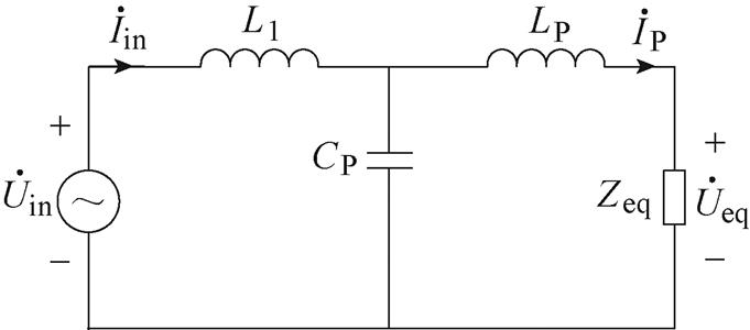
图2 原边等效电路
Fig.2 Primary side equivalent circuit
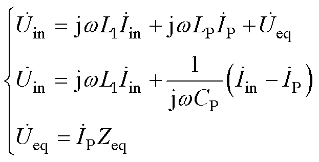 (1)
(1)
求解式(1)可得原边输出电压为
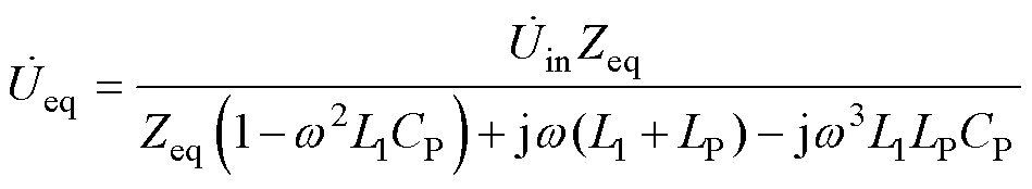 (2)
(2)
输出电流为
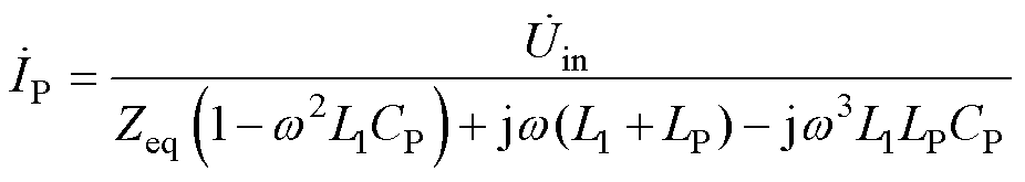 (3)
(3)
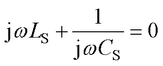
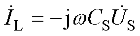
由式(3)可知,当系统角频率w 满足式(4)时,LCL电路拓扑的输出与负载无关,可实现恒流输出,此时输出电流化简后如式(5)所示。
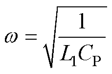 (4)
(4)
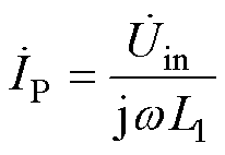 (5)
(5)
由1.1节分析可知,原边LCL的输出可等效为恒流源,则在副边感应的恒压源为 。恒流时开关S为导通状态,副边恒流输出等效电路如图3所示。
令 ,对图3分析可知
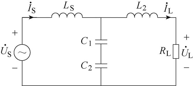
图3 副边恒流输出等效电路
Fig.3 Secondary side constant current output equivalent circuit
 (6)
(6)
若式(6)满足
 (7)
(7)
则副边输出电流的大小与负载无关,输出电流表达式为
 (8)
(8)
因此,在原边输出电流保持不变的条件下,可以实现副边恒流输出。
副边恒压输出等效电路如图4所示,此时开关状态为断开,辅助电感L3接入电容支路,与额外补偿电容C1组成LC滤波器,L3与C1满足
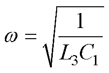 (9)
(9)
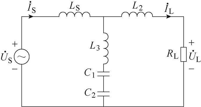
图4 副边恒压输出等效电路
Fig.4 Secondary side constant voltage output equivalent circuit
电容支路对外等效为电容C2,对图4副边LCL电路列写KVL方程,通过对方程求解可求得输出电压表达式为
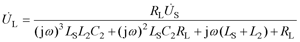 (10)
(10)
定义d=LS/L2,当式(10)满足
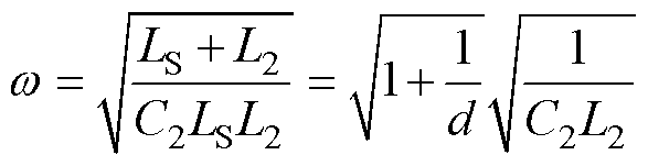 (11)
(11)
输出电压为
 (12)
(12)
LCL副边可实现恒压输出,若使得恒流向恒压转变过程中系统频率不变,则电容C2需满足
 (13)
(13)
系统恒流向恒压切换时,谐振网络的参数取值不仅要满足式(13),还需要保证切换过程中电池等效负载两端的电压不会发生突变。因此,需要对平滑切换的条件进行分析。
设系统在t时刻开始从恒流向恒压切换,此时等效负载电阻为RL,则恒流模式时副边输出的电压为 ,恒压模式时副边输出的电压为
 ,根据式(8)和式(12)可得和
 分别为
分别为
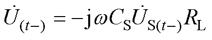 (14)
(14)
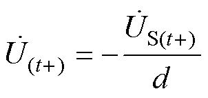 (15)
(15)
切换瞬间等效负载电阻RL不会发生跳变,令式(14)和式(15)的模值相等,得到切换时电压稳定的条件为
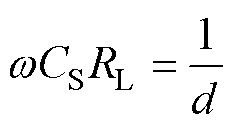 (16)
(16)
基于双边LCL变补偿参数的磁耦合谐振式无线充电系统等效电路如图5所示,假设Ib为系统恒流充电模式时充电电流,Vb为恒压充电模式下充电电压,Rb为电池等效负载,E为系统输入直流电压。
逆变器输出电压基波的有效值Vab为
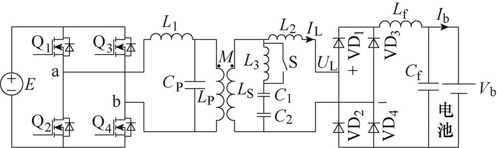
图5 无线充电系统等效电路
Fig.5 Equivalent circuit of wireless charging system
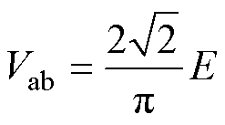 (17)
(17)
整流桥输入电压和输入电流的有效值UL和IL分别为
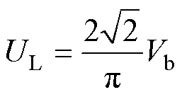 (18)
(18)
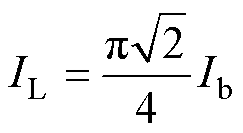 (19)
(19)
整流桥和电池等效为副边的负载RL为
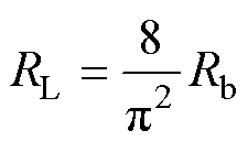 (20)
(20)
系统原边需要实现恒流,根据式(4),可得原边补偿电容取值为
 (21)
(21)
副边恒流时,将式(5)、式(17)和式(19)代入式(8)可得 和
和 分别为
分别为
 (22)
(22)
 (23)
(23)
副边恒压时,根据式(13)可得C2为
 (24)
(24)
根据式(22)和式(24)得出C1为
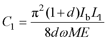 (25)
(25)
根据式(11)和式(24)可得副边电感L2为
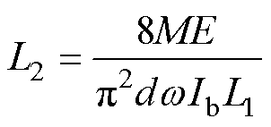 (26)
(26)
根据式(9)和式(25)可得辅助电感L3为
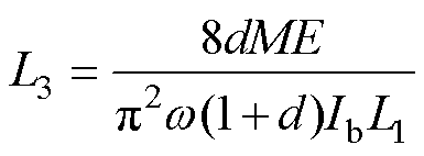 (27)
(27)
式(22)~式(27)给出了磁耦合谐振式无线充电系统谐振网络参数的选取方法,按此方法可设计出所需要充电电流和充电电压的无线充电系统。
图6给出了系统通过开关投切电感的控制逻辑,参考电压Vref为系统恒压充电模式下的电压值。当Vb<Vref时,开关S处于闭合状态,其余情况开关S处于断开状态。
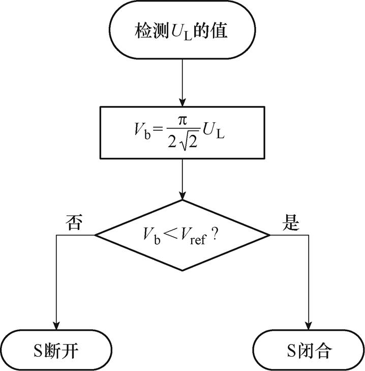
图6 开关控制逻辑
Fig.6 Switch control logic
为了验证理论分析的可行性,根据图5电路结构搭建了无线充电系统的仿真模型,具体系统参数见表1,系统输出的电压和电流如图7所示。
表1 系统参数
Tab.1 System parameters

参 数数 值 输入电压E/V72 系统工作频率f/kHz80 初级电感L1/mH13.8 初级补偿电容CP/mF0.29 原边线圈自感LP/mH217.53 副边线圈自感LS/mH231.46 次级电感L2/mH117.2 辅助电感L3/mH156.05 次级补偿电容C1/nF25.5 附加串联电容C2/nF51.2 线圈距离l/mm30 互感M/mH82.33

图7 系统输出的电压和电流
Fig.7 Voltage and current output by the system
在系统处于恒流模式时输出电压、电流仿真波形如图7a所示,当负载从15W 上升到20W 时,系统输出电流保持不变,输出电压由45V上升到60V。图7b为恒压模式输出电压电流的波形,负载由100W 降到20W 时,系统输出电压保持不变,输出电流由0.6A上升到3A。根据上述分析可以得出设计的系统在负载跳变时可以保持恒流和恒压特性。
图8给出了投切电感前后副边输出电流波形及其畸变率,可以看出,当恒流时副边输出电流受高次谐波影响较大,波形畸变率为15.43%,在恒压模式下,L3和C1组成滤波器,可以有效改善副边输出电流波形,波形畸变率降为1.24%左右。因此在副边投切电感不仅可以实现系统的恒压输出,而且还能够改善输出电流波形,提高系统稳定性和效率。
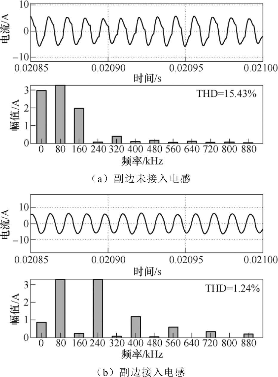
图8 副边输出电流波形及其畸变率
Fig.8 Secondary side output current waveforms and its distortion rate
图9为根据仿真参数搭建的实验平台,整个无线充电系统额定功率为180W,恒流充电时充电电流为3A,电压由45V上升到额定电压60V时转为恒压充电,此时充电电流从3A逐渐下降到截止电流0.1A。电池对于整个系统相当于一个变化的负载电阻Rb。图10为恒流充电模式下,逆变器输出电压Uab、输出电流Iab、充电电压Vb、充电电流Ib的波形。图10a为恒流充电起始状态,系统开始以3.03A电流充电,电池两端电压为44.84V,此时电池等效电阻大小约为14.8W,电池两端电压开始增加;图10b为恒流充电结束状态,此时电池电压到达60.22V,充电电流为2.98A,电池等效负载电阻约为20.2W,充电电流相比于起始阶段电流偏差为1.65%。可以看出,系统工作在恒流充电模式下电流略微波动,满足电池恒流充电的要求。
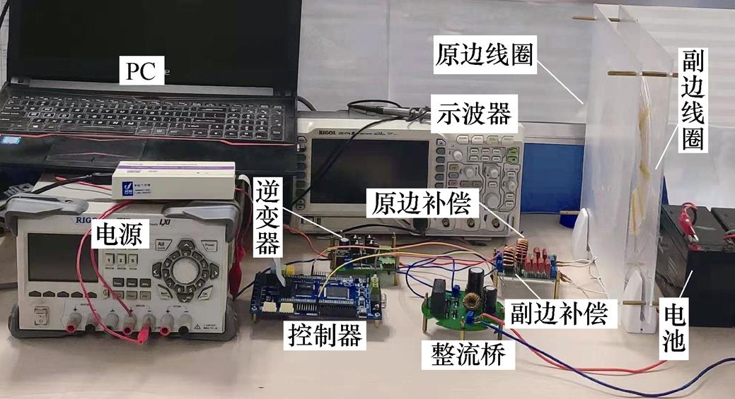
图9 实验平台
Fig.9 Experimental platform
为了验证系统可以实现恒流充电向恒压充电的平滑过渡,对系统充电模式转换时的充电电压、电流的波形进行了测量,恒流向恒压切换时,Vb和Ib的波形如图11所示,系统充电电压在充电模式转换时出现了约250ms的抖动,此时系统最高充电电压可以达到62.45V,之后电压恢复为60.32V左右,电压偏差为3.3%左右。由于进入恒压充电模式,系统充电电流不再继续保持不变,开始从3A逐渐下降。
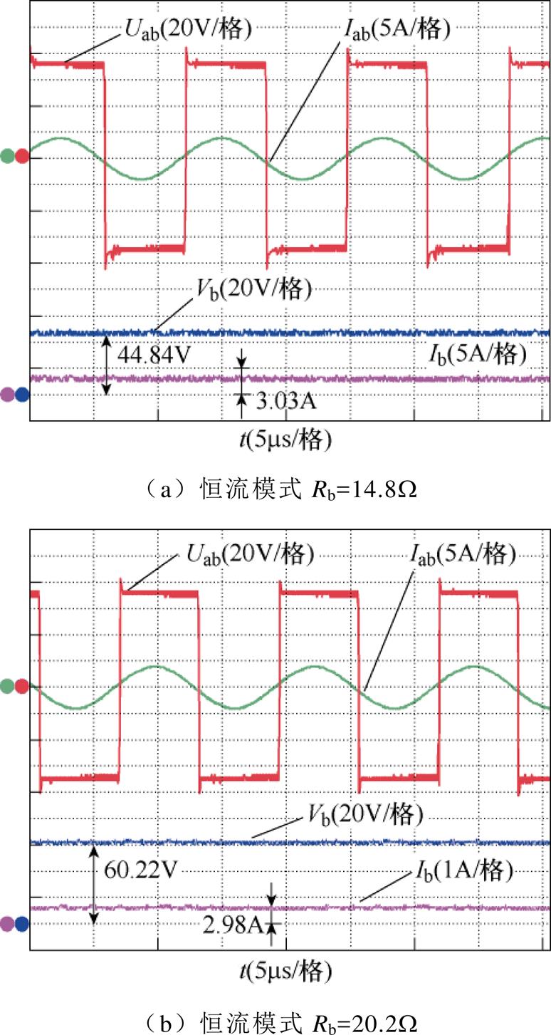
图10 恒流模式下Rb为14.8W 和20.2W 时,Uab、Iab、Vb和Ib的波形
Fig.10 Rb is 14.8W and 20.2W in constant current mode, waveforms of Uab、Iab、Vb and Ib
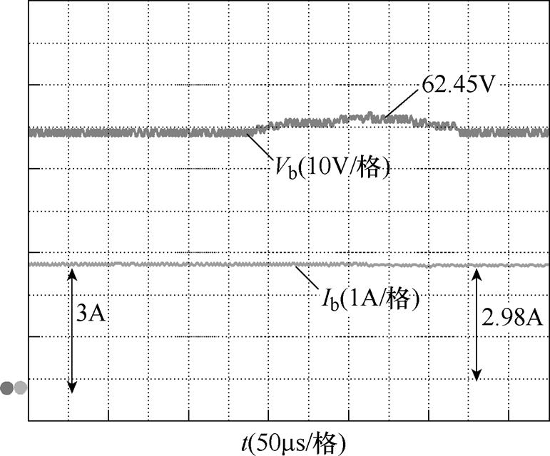
图11 恒流向恒压切换时Vb和Ib的波形
Fig.11 Waveforms of Vb and Ib when switching from constant current to constant voltage
图12为恒压充电模式下,逆变器输出电压Uab、输出电流Iab、充电电压Vb、充电电流Ib的波形。图12a为恒压充电的前期状态,电池等效负载为25W,电池充电电压Vb=60.32V,充电电流Ib=2.41A;图12b为恒压充电后期状态,此时电池等效负载为100W,电池充电电流约为0.61A,充电电压为61.45V,相比于恒压充电前期电压偏差为1.8%,可以看出,系统工作在恒压充电模式下电压波动较小,满足恒压充电的要求。
图13所示为电池在充电过程中,系统充电效率与充电功率随着负载的变化而变化的曲线。当系统处于恒流模式时,电池电压迅速升高,此时,系统充电功率与充电效率也随着负载变大而迅速增大。当电池电压达到充电电压Vref时,系统达到最大充电效率(91.2%)和最大充电功率(179.4W),并将从CC模式切换为CV模式。在CV模式下,随着负载继续增大,充电电流呈指数衰减,在此过程中,系统充电功率和充电效率也逐渐下降。

图12 恒压模式下Rb为25W 和100W 时,Uab、Iab、Vb和Ib的波形
Fig.12 Rb is 25W and 100W in constant voltage mode, waveforms of Uab、Iab, Vb and Ib
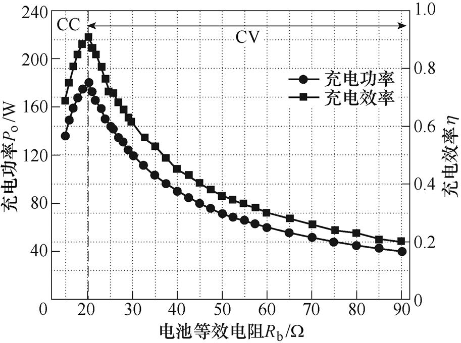
图13 系统充电效率和充电功率曲线
Fig.13 System charging efficiency and charging power curves
对于无线充电系统,距离对系统效率的影响同样不可忽略,本文所研究的距离为30mm,距离对该系统的影响主要考虑线圈的横向偏移和纵向偏移。为测试系统稳定性,设定负载为20W,原、副边线圈初始位置中心轴在同一条直线上,固定原边线圈,对副边线圈位置标记为坐标原点,并对副边线圈做纵向偏移和横向偏移,线圈相互靠近时偏移量记为负,相互远离时偏移量记为正,其输出电流、电压及效率变化见表2和表3。
表2 纵向偏移时系统输出电流、电压和效率的变化
Tab.2 System output current, voltage and efficiency change table when longitudinal shift
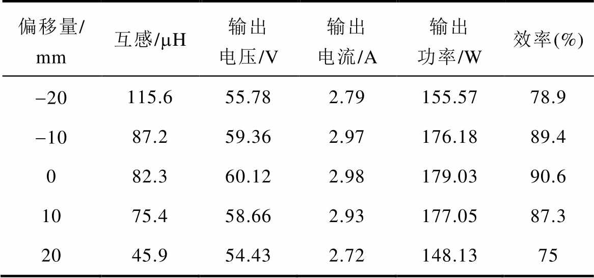
偏移量/ mm互感/mH输出电压/V输出电流/A输出功率/W效率(%) -20115.655.782.79155.5778.9 -1087.259.362.97176.1889.4 082.360.122.98179.0390.6 1075.458.662.93177.0587.3 2045.954.432.72148.1375
表3 横向偏移时系统输出电流、电压和效率的变化
Tab.3 System output current, voltage and efficiency change table when lateral shift
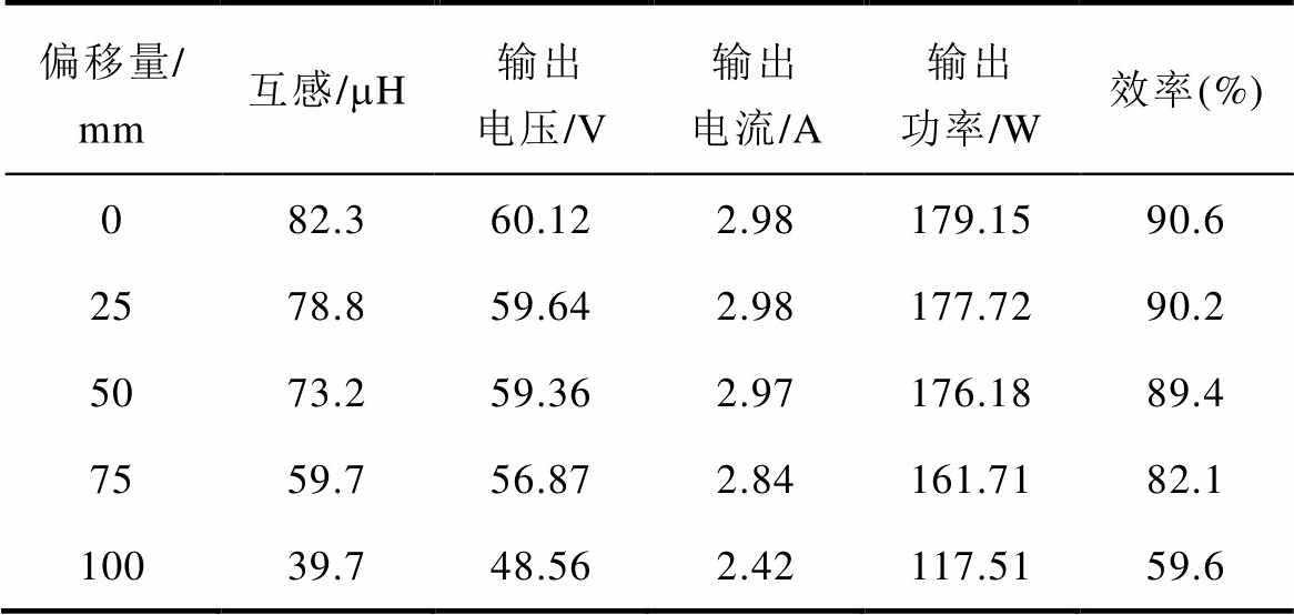
偏移量/ mm互感/mH输出电压/V输出电流/A输出功率/W效率(%) 082.360.122.98179.1590.6 2578.859.642.98177.7290.2 5073.259.362.97176.1889.4 7559.756.872.84161.7182.1 10039.748.562.42117.5159.6
根据表2所示,线圈在纵向偏移时,无论是靠近还是远离坐标原点,线圈的效率均减小,且当偏移量小于10mm时,系统依然能够稳定输出;当偏移量大于10mm时,线圈互感的变化使系统失谐,导致稳定性下降。
当线圈发生横向偏移时,由表3可知,偏移量小于50mm时,系统电压电流变化量较小,系统稳定性较好;当偏移量大于50mm时,系统输出不能满足设计要求。综上所述,系统在纵向偏移10mm,横向偏移50mm范围内依然能够稳定输出。
表4为本文提出的无线充电系统与之前无线充电系统的对比,文献[27]虽然使用开关器件和谐振组件较少,但是系统原边和副边需要进行通信,整体的动态响应比较慢,并且效率比较低。文献[31-32]使用了多个开关器件,整个系统控制模块比较复杂,实现难度高。文献[30]系统结构简单,但是整体效率较低。可以看出,本文所提无线充电系统所用开关器件少、系统结构简单、控制方便、整体稳定性和效率较高。
表4 提出的无线充电系统与之前的研究比较
Tab.4 Comparison of the proposed wireless charging system with the previous system

参考文献电感个数电容个数开关个数是否通信效率(%) 本文331否91.2 [27]031是80 [30]131否87 [31]142否87 [32]433否89.4
本文基于双边LCL电路设计了一种变补偿参数的磁耦合谐振式无线充电系统,对提出的新型双边LCL变补偿拓扑进行理论分析,得出了实现恒流恒压的条件,基于此设计了系统谐振网络参数,然后通过仿真和实验对该系统进行验证,得出了以下结论:
1)系统可以实现恒流和恒压输出,在额定功率180W、恒流3A和恒压60V的充电模式下,充电电流和充电电压变化率分别为1.65%和1.8%,受负载变化影响较低,满足电池充电条件。
2)恒压输出时,谐振网络中接入的LC滤波器可以改善系统输出电流波形,降低波形畸变率,提高系统的稳定性和效率。
3)设计的系统仅需改变副边补偿参数,无需原、副边之间的通信,降低了无线充电系统的复杂性和控制难度。
参考文献
[1] 薛明, 杨庆新, 章鹏程, 等. 无线电能传输技术应用研究现状与关键问题[J]. 电工技术学报, 2021, 36(8): 1547-1568.
Xue Ming, Yang Qingxin, Zhang Pengcheng, et al. Application status and key issues of wireless power transmission technology[J]. Transactions of China Electrotechnical Society, 2021, 36(8): 1547-1568.
[2] Hui S Y. Planar wireless charging technology for portable electronic products and qi[J]. Proceedings of the IEEE, 2013, 101(6): 1290-1301.
[3] Li Yong, Mai Ruikun, Lin Tianren, et al. A novel WPT system based on dual transmitters and dual receivers for high power applications: analysis, design and implementation[J]. Energies, 2017, 10(2): 174.
[4] 王彤辉, 郎宝华. 小功率智能电器的无线供电控制系统[J]. 单片机与嵌入式系统应用, 2019, 19(8): 60-64.
Wang Tonghui, Lang Baohua. Wireless power supply control system of low-power intelligent appliances[J]. Microcontrollers & Embedded Systems, 2019, 19(8): 60-64.
[5] 蔡春伟, 姜龙云, 陈轶, 等. 基于正交式磁结构及原边功率控制的无人机无线充电系统[J]. 电工技术学报, 2021, 36(17): 3675-3684.
Cai Chunwei, Jiang Longyun, Chen Yi, et al. Wireless charging system of unmanned aerial vehicle based on orthogonal magnetic structure and primary power control[J]. Transactions of China Electrotechnical Society, 2021, 36(17): 3675-3684.
[6] RamRakhyani A K, Mirabbasi S, Chiao M. Design and optimization of resonance-based efficient wire- less power delivery systems for biomedical implants[J].IEEE Transactions on Biomedical Circuits and Systems, 2011, 5(1): 48-63.
[7] 陈海燕, 高晓琳, 杨庆新, 等. 用于人工心脏的经皮传能系统耦合特性及补偿的研究[J]. 电工电能新技术, 2008, 27(2): 59-62.
Chen Haiyan, Gao Xiaolin, Yang Qingxin, et al. Study on coupling characteristics and compensation of transcutaneous energy transmission system for artificial heart [J]. Advanced Technology of Electrical Engineering and Energy, 2008, 27(2): 59-62.
[8] Yoo J, Yan Long, Lee S, et al. A 5.2mW self- configured wearable body sensor network controller and a 12mW 54.9% efficiency wirelessly powered sensor for continuous health monitoring system[C]// IEEE International Solid-State Circuits Conference, San Francisco, 2009: 290-291.
[9] 张献, 任年振, 杨庆新, 等. 电动汽车无线充电自整定控制[J]. 电工技术学报, 2020, 35(23): 4825- 4834.
Zhang Xian, Ren Nianzhen, Yang Qingxin, et al. Research on self-tuning control strategy of wireless charging for electric vehicles[J]. Transactions of China Electrotechnical Society, 2020, 35(23): 4825- 4834.
[10] 吴理豪, 张波. 电动汽车静态无线充电技术研究综述(上篇)[J]. 电工技术学报, 2020, 35(6): 1153- 1165.
Wu Lihao, Zhang Bo. Overview of static wireless charging technology for electric vehicles: part Ⅰ[J]. Transactions of China Electrotechnical Society, 2020, 35(6): 1153-1165.
[11] 吴理豪, 张波. 电动汽车静态无线充电技术研究综述(下篇)[J]. 电工技术学报, 2020, 35(8): 1662-1678.
Wu Lihao, Zhang Bo. Overview of static wireless charging technology for electric vehicles: part Ⅱ[J]. Transactions of China Electrotechnical Society, 2020, 35(8): 1662-1678.
[12] 赵靖英, 周思诺, 崔玉龙, 等. LCL型磁耦合谐振式无线电能传输系统的设计方法研究与实现[J]. 高电压技术, 2019, 45(1): 228-235.
Zhao Jingying, Zhou Sinuo, Cui Yulong, et al. Research and implementation on design method for LCL type magnetically-coupled resonant wireless power transfer system[J]. High Voltage Engineering, 2019, 45(1): 228-235.
[13] Qu Xiaohui, Han Hongdou, Wong S C, et al. Hybrid IPT topologies with constant-current or constant- voltage output for battery charging applications[J]. IEEE Transactions on Power Electronics, 2015, 30(11): 6329-6337.
[14] 张辉, 王换民, 李宁, 等. 电动汽车无线充电混合补偿拓扑电路分析[J]. 电力系统自动化, 2016, 40(16): 71-75.
Zhang Hui, Wang Huanmin, Li Ning, et al. Analysis on hybrid compensation topology circuit for wireless charging of electric vehicles[J]. Automation of Electric Power Systems, 2016, 40(16): 71-75.
[15] Wang C S, Stielau O H, Covic G A. Design considerations for a contactless electric vehicle battery charger[J]. IEEE Transactions on Industrial Electronics, 2005, 52(5): 1308-1314.
[16] Wu H H, Gilchrist A, Sealy K D, et al. A high efficiency 5kW inductive charger for EVs using dual side control[J]. IEEE Transactions on Industrial Informatics, 2012, 8(3): 585-595.
[17] Fu Minfan, Yin He, Zhu Xinen, et al. Analysis and tracking of optimal load in wireless power transfer systems[J]. IEEE Transactions on Power Electronics, 2015, 30(7): 3952-3963.
[18] Budhia M, Covic G A, Boys J T. Design and opti- mization of circular magnetic structures for lumped inductive power transfer systems[J]. IEEE Transa- ctions on Power Electronics, 2011, 26(11): 3096- 3108.
[19] Berger A, Agostinelli M, Vesti S, et al. A wireless charging system applying phase-shift and amplitude control to maximize efficiency and extractable power[J]. IEEE Transactions on Power Electronics, 2015, 30(11): 6338-6348.
[20] Li Hongchang, Li Jie, Wang Kangping, et al. A maximum efficiency point tracking control scheme for wireless power transfer systems using magnetic resonant coupling[J]. IEEE Transactions on Power Electronics, 2015, 30(7): 3998-4008.
[21] Berger A, Agostinelli M, Vesti S, et al. Phase-shift and amplitude control for an active rectifier to maximize the efficiency and extracted power of a wireless power transfer system[C]//IEEE Applied Power Electronics Conference and Exposition (APEC), Charlotte, 2015: 1620-1624.
[22] Zhang Wei, Wong S C, Tse C K, et al. Design for efficiency optimization and voltage controllability of series-series compensated inductive power transfer systems[J]. IEEE Transactions on Power Electronics, 2014, 29(1): 191-200.
[23] Liu Nan, Habetler T G. Design of a universal indu- ctive charger for multiple electric vehicle models[J]. IEEE Transactions on Power Electronics, 2015, 30(11): 6378-6390.
[24] Zheng Cong, Lai J S, Chen Rui, et al. High efficiency contactless power transfer system for electric vehicle battery charging application[J]. IEEE Journal of Emerging and Selected Topics in Power Electronics, 2015, 3(1): 65-74.
[25] Nagatsuka Y, Ehara N, Kaneko Y, et al. Compact con- tactless power transfer system for electric vehicles[C]// The 2010 International Power Electronics Conference, Sapporo, 2010: 807-813.
[26] Wang C S, Covic G A, Stielau O H. Power transfer capability and bifurcation phenomena of loosely coupled inductive power transfer systems[J]. IEEE Transactions on Industrial Electronics, 2004, 51(1): 148-157.
[27] 麦瑞坤, 陈阳, 刘野然. 基于变补偿参数的IPT恒流恒压电池充电研究[J]. 中国电机工程学报, 2016, 36(21): 5816-5821, 6024.
Mai Ruikun, Chen Yang, Liu Yeran. Compensation capacitor alteration based IPT battery charging application with constant current and constant voltage control[J]. Proceedings of the CSEE, 2016, 36(21): 5816-5821, 6024.
[28] 景玉军, 张冰战. 双LCL谐振型电动汽车无线充电系统研究[J]. 电力电子技术, 2017, 51(7): 89-92. Jing Yujun, Zhang Bingzhan. Research on electric vehicle charging based on double LCL compensation of wireless power transfer system[J]. Power Electro- nics, 2017, 51(7): 89-92.
[29] 侯春, 朱旺, 水恒琪, 等. 基于LCL-LC/LCL混合补偿的多电动汽车恒流恒压无线充电系统特性分析[J]. 电工电能新技术, 2018, 37(11): 58-68.
Hou Chun, Zhu Wang, Shui Hengqi, et al. Characteri- stic analysis of constant current and voltage wireless charging system for multi-electric vehicles based on LCL-LC/LCL hybrid compensation[J]. Advanced Technology of Electrical Engineering and Energy, 2018, 37(11): 58-68.
[30] Zhang Hailong, Chen Yafei, Park S J, et al. A hybrid compensation topology with single switch for battery charging of inductive power transfer systems[J]. IEEE Access, 2019, 7: 171095-171104.
[31] Hwang S H, Chen Yafei, Zhang Hailong, et al. Recon- figurable hybrid resonant topology for constant current/voltage wireless power transfer of electric vehicles[J]. Electronics, 2020, 9(8): 1323.
[32] 刘帼巾, 白佳航, 崔玉龙, 等. 基于双LCL变补偿参数的磁耦合谐振式无线充电系统研究[J]. 电工技术学报, 2019, 34(8): 1569-1579.
Liu Guojin, Bai Jiahang, Cui Yulong, et al. Double- sided LCL compensation alteration based on MCR- WPT charging system[J]. Transactions of China Electrotechnical Society, 2019, 34(8): 1569-1579.
Research and Analysis of Resonant Wireless Charging System Based on Bilateral LCL Variable Compensation Parameters
Abstract In wireless charging, the switching process from constant current charging mode to constant voltage charging mode is complicated, and the control circuit design is difficult. Therefore, this paper designs a magnetic coupling resonant wireless charging system with variable compensation parameters based on the bilateral LCL topology. The system only needs to switch the additional inductance of the secondary side to complete the smooth conversion from constant current charging to constant voltage charging, thereby eliminating the communication between the original secondary side, reducing the complexity of control circuit design and improving the overall efficiency and stability of the wireless charging system. Firstly, the paper theoretically analyzes of the bilateral LCL variable compensation topology, and derives the conditions for the constant current and constant voltage of the primary side of the system. Then, through the transient analysis of the system constant current to constant voltage switching process, the smooth transition of the switching is realized. Finally, the designed wireless charging system is simulated and experimentally verified. The results show that the system can achieve smooth switching from constant current to constant voltage, and the charging current deviation and charging voltage deviation are 1.65% and 1.8% respectively under the charging conditions of constant current 3A and constant voltage 60V, which meet the battery charging. requirements. In the constant voltage charging mode, the output current waveform of the secondary side resonant network of the system is significantly improved, and the waveform distortion rate is reduced from 15.43% to 1.24%.
keywords:Wireless charging, bilateral LCL, constant current, constant voltage
DOI: 10.19595/j.cnki.1000-6753.tces.211330
中图分类号:TM46
国家自然基金面上项目(51777167)和国家自然基金青年项目(51604217)资助。
收稿日期 2021-08-23
改稿日期 2021-11-01
王党树 男,1976年生,副教授,研究方向为电力电子技术。E-mail: wangdangshu@126.com
董 振 男,1997年生,硕士研究生,研究方向为电力电子技术。E-mail: 1174762596@qq.com(通信作者)
(编辑 陈 诚)