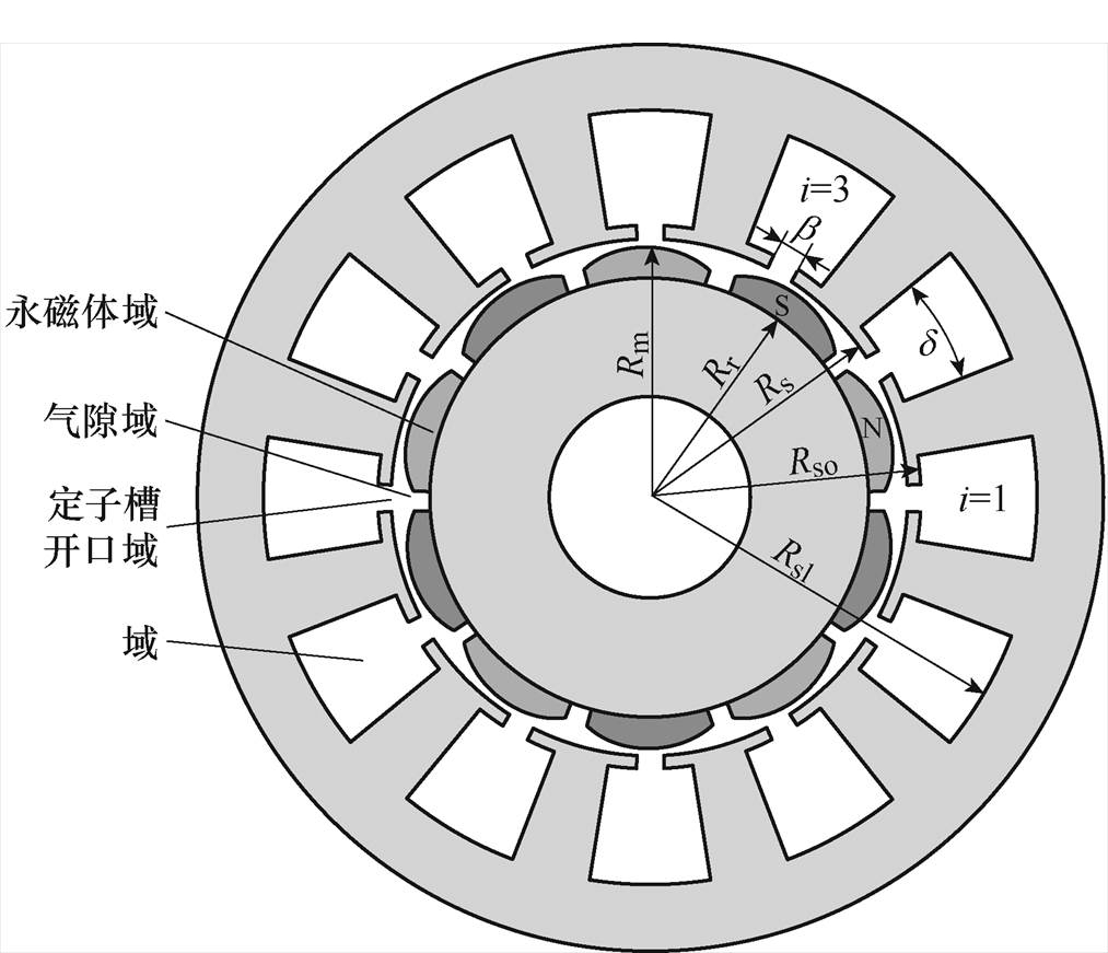
图1 磁极偏心式永磁同步电机简化模型
Fig.1 Simplified model of pole eccentric permanent magnet synchronous motor
摘要 工业机器人与数控机床用永磁同步电机设计过程中为追求反电动势的正弦性和低转矩脉动,常采用面包型或偏心削极的不均匀气隙结构,该文基于微分原理对不均匀气隙结构转子磁极进行径向等极弧分段,在二维极坐标下将电机结构划分为永磁体、气隙、槽开口和定子槽四个精确子域的解析模型,并建立泊松方程和拉普拉斯方程,通过分离变量法与傅里叶级数法求解偏微分方程,通过边界条件对各子域谐波系数求解以得到各分段磁极磁场分布,然后基于积分原理对其等效叠加得到电机二维磁场分布结果。该解析方法同时考虑到瓦片型、偏心式与面包型磁极转子结构,可以计算任意单元数电机的空载、电枢及负载的磁场特性,并在此基础上计算转矩和空载反电动势特性。通过样机测试结果和有限元仿真结果与解析结果进行比较,验证解析方法的准确性,能够快速指导电机设计。
关键词:永磁同步电机 子域解析法 不均匀气隙 等极弧分段 磁场性能
永磁电机凭借其高转矩密度、高效率等优势逐渐在工业机器人与数控机床场合广泛应用,其气隙磁通密度及反电动势(Electromagnetic Force, EMF)波形对电机性能和效率的影响很大,因此正确而快速有效地分析电机磁场性能是电机设计的基础。精确子域解析法作为准确高效分析电机电磁场的方法近年来被国内外学者广泛运用,其中Zhu Ziqiang和Wu Lijian等分别提出了表贴式精确子域模型[1]和改进模型[2]解析方法,A. Rahideh等提出无槽和开槽内外转子的磁钢表面插入式,以及交替极结构的二维磁场解析方法[3-6],T. Lubin等提出表贴式和表面插入式半闭口槽结构精确子域解析法[7-8],国内亦有众多学者以精确子域法对不同结构电机进行磁场计算分析[9-12]。但上述文献都是以气隙均匀的瓦片型磁钢结构进行子域解析计算。
工业机器人与数控机床驱动电机对反电动势正弦度和低转矩波动性能要求较高,面包型或偏心削极结构等特殊磁钢形状引起不均匀气隙的表贴式永磁同步电机成为研究的热点[13-19]。文献[13]提出多边形转子轭结构的空载磁场解析模型,对空载磁通密度与磁通密度谐波进行分析;文献[14]利用卡特系数考虑定子开槽影响,推导出负载下偏心磁极径向磁通密度解析模型,以偏心距和极弧系数对磁通密度波形进行优化设计,并通过样机测试结果对解析和有限元结果验证;文献[15]提出两种凸极不等厚磁极形状的直口槽结构精确子域解析模型,并分析磁极尺寸变化对电机性能的影响;文献[16-17]都以等效面电流法对偏心磁极结构进行数学建模,分析空载气隙磁通密度情况;文献[18-19]将磁极分段等效,分别对无槽结构磁场和电机空载磁通密度的优化设计进行分析。上述文献以不同磁场解析方法对单一特殊磁钢形状永磁电机进行建模和磁场解析计算,未能统一考虑面包型和偏心削极结构等特殊磁钢形状引起不均匀气隙的表贴式永磁同步电机准确磁场解析计算。
本文以完全子域解析法对不均匀气隙结构表贴式永磁同步电机进行建模,通过引入矢量磁位,建立永磁体、气隙、槽开口、定子槽四个子域解析模型,根据微分原理对不均匀气隙结构的永磁体等效划分为极弧均等但半径不同的若干段磁极,利用傅里叶级数法、分离变量法求解分段磁极磁场分布,依据积分原理对各段磁极磁场等效叠加得到电机二维磁场结果,本文解析方法能同时考虑到瓦片型、偏心式和面包型磁极形状,可计算任意单元数结构电机的空载和负载下电机磁场特性,以研制的一台24极36槽样机进行实验,根据实验测试和有限元仿真结果验证解析法计算结果的准确性。
本文对表贴式内转子不均匀气隙结构永磁同步电机进行建模,电机的二维简化模型如图1所示,基于精确子域模型分析原理,将电机模型划分为永磁体、气隙、定子槽开口和定子槽四个子域。为便于对模型分析,作出如下基本假设:
图1 磁极偏心式永磁同步电机简化模型
Fig.1 Simplified model of pole eccentric permanent magnet synchronous motor
(1)永磁体的电导率为0,磁导率为实际相对磁导率,其退磁曲线为直线,且磁极之间空气的磁导率与永磁体磁导率相同。
(2)定、转子铁心的磁导率为无穷大。
(3)忽略电机端部影响。
(4)定子槽形状为如图1所示的理想的半开口槽。
转子结构采用如图2所示的不均匀气隙结构时,由于永磁体与气隙子域之间的边界条件较为复杂,以及磁化强度也难以用简单的表达式表示,基于方程求解更加困难,所以针对永磁体形状的改变采用新的方法等效计算。
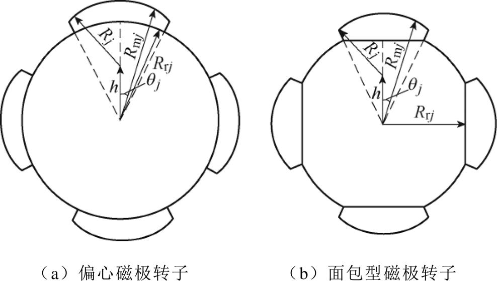
图2 不均匀气隙转子简化模型
Fig.2 Simplified model of rotor with nonuniform air gap
本文基于微积分思想,将永磁体极弧域进行圆周区域分割,偏心式磁极等效结构如图3所示,面包型磁极等效结构如图4所示。Rj为偏心半径,h为偏心距,qj为第j段磁极与磁极中线的夹角,hm为永磁体最大厚度;当分割段数足够多时,每小段永磁体形状就可看作为径向瓦片型结构。
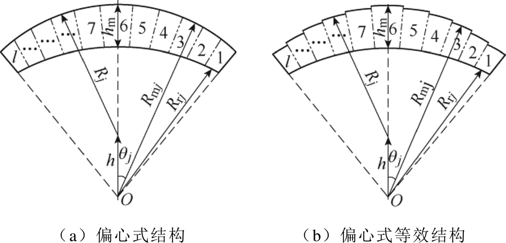
图3 偏心式磁极等效结构
Fig.3 Equivalent structure of eccentric magnetic pole
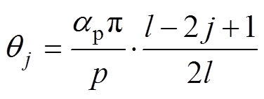
l为永磁体分段数,ap为永磁体极弧系数,p为电机极对数,则第j段磁极与永磁体中线夹角 可表示为
可表示为
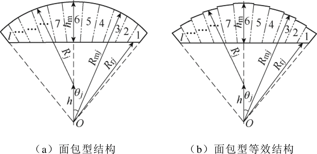
图4 面包型磁极等效结构
Fig.4 Equivalent structure of bread type magnetic pole
 (1)
(1)
根据三角形余弦定理求得第j段磁极的外半径Rmj为
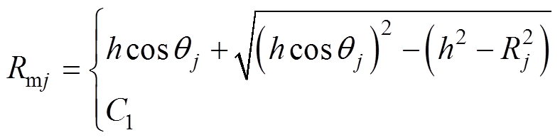 (2)
(2)
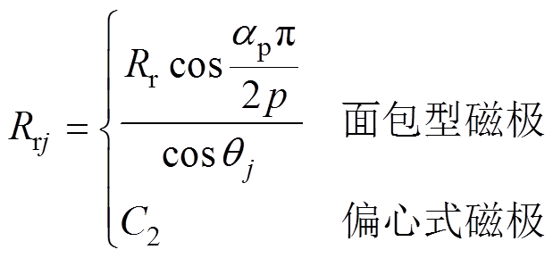
对于不同形状的两种永磁体,第j段磁极内半径Rrj可表示为
 (3)
(3)
式中,Rr为转子铁心最大外径;Rm为永磁体最大外径,当每段磁极外径Rmj和内径Rrj同时为常数C1和C2时,该磁极形状为瓦片型结构。不同时刻下第j段磁极中心位置角 为
为
 (4)
(4)
式中,wr为转子角速度。
当t =0时刻,磁极中心位置角aj和每小段磁极的极弧系数apj可表示为
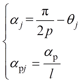 (5)
(5)
永磁体的磁化强度见附录式(A1)和式(A2)。
由图1所示简化模型结构,槽数为Q的第i号槽以及槽开口的中心位置角可表示为
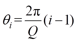 (6)
(6)
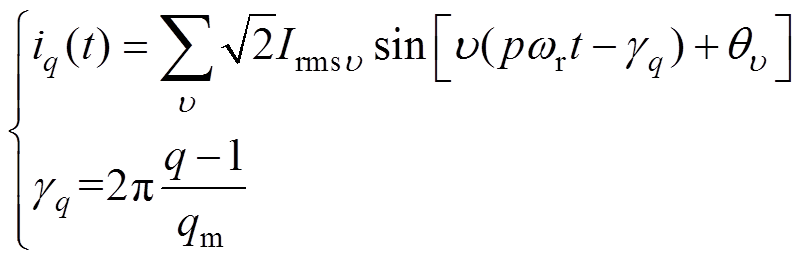
对多相绕组条件下,第q相线圈电流可表示为
 (7)
(7)
式中, 为电流谐波阶数;
 和
和 分别为各阶次电流的有效值和移相角;qm为电机相数;
 为q相相移角度。
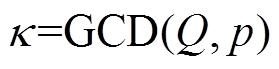
本文考虑单元单机模型计算,单元数 定义为槽数Q和极对数p的最大公因数,即
 (8)
(8)
对于36槽24极结构,绕组排布方式如图5所示。
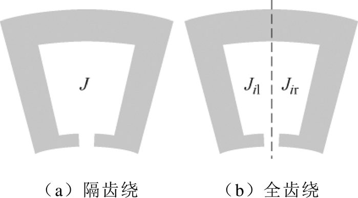
图5 绕组排布方式
Fig.5 Winding arrangement
采用图5给出的全齿绕集中绕组,其单元电机绕组排布矩阵 为
为
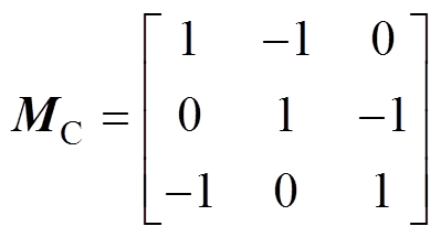 (9)
(9)
式中,1和-1为电流流入流出的方向。槽电流密度表示为
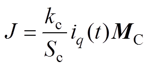 (10)
(10)
式中,kc为导线填充系数;Sc为导线横截面积。
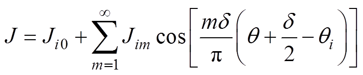
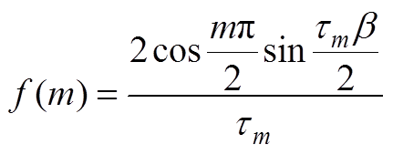
第i槽左、右线圈电流密度Jil、Jir可以表示为
 (11)
(11)
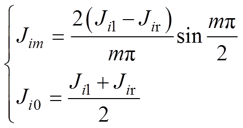 (12)
(12)
式中, 为定子槽宽角;m为电流密度谐波阶数,也是定子槽谐波阶数;Ji0和Jim分别为第i槽中电流密度傅里叶级数常系数和m阶系数。
在永磁体域和定子槽域的有源区域内,及气隙域和槽开口域的无源域内,通过引入矢量磁位Arj,Asli,Aair和Asoi,建立对应的泊松方程和拉普拉斯方程[1,2,8],各子域的偏微分方程为
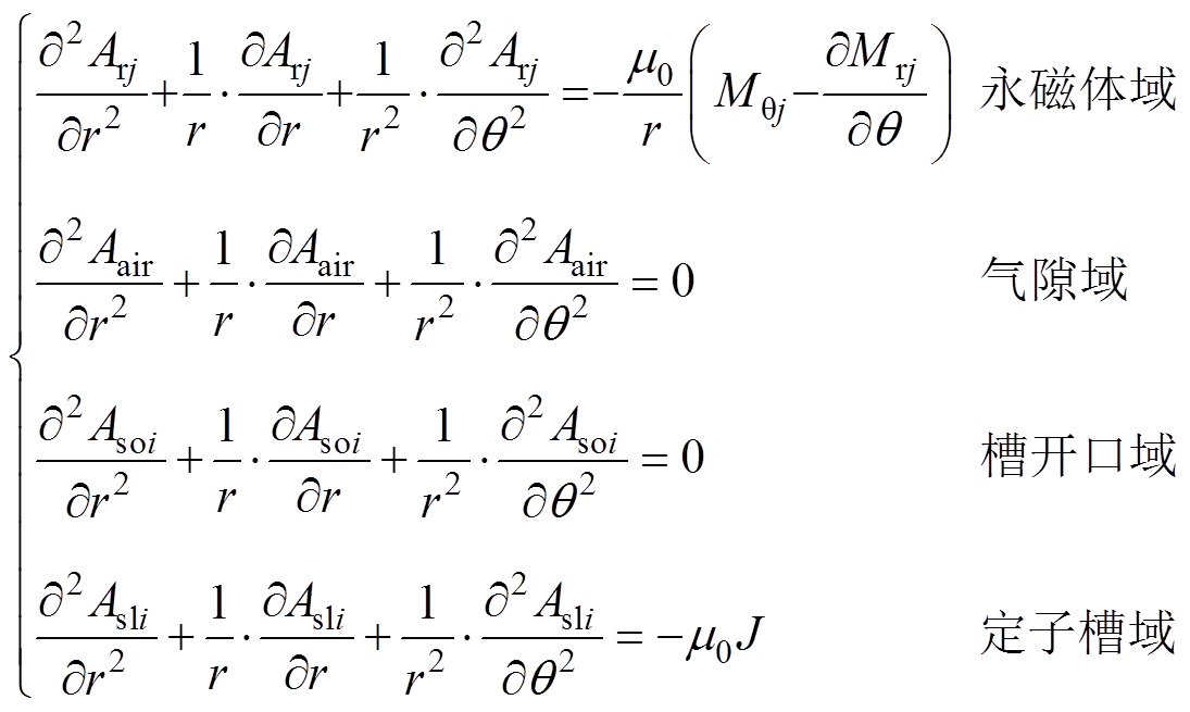 (13)
(13)
根据相邻两介质边界上矢量磁位的法向分量连续、切向分量相等的分布规则,在永磁体区域,其边界条件可表示为
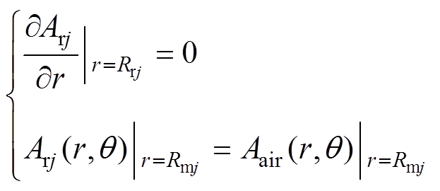 (14)
(14)
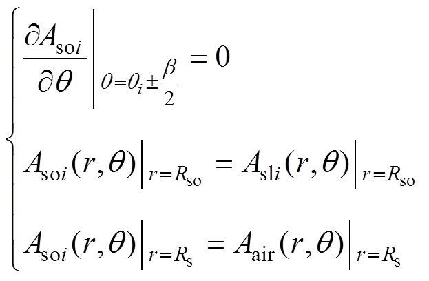
气隙区域边界条件为
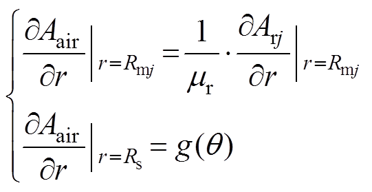 (15)
(15)
其中
 (16)
(16)
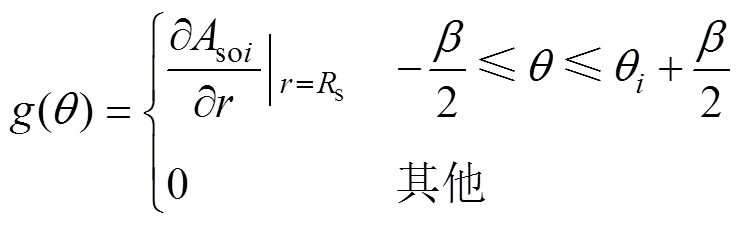
槽开口区域边界条件为
 (17)
(17)
定子槽区域其边界条件为
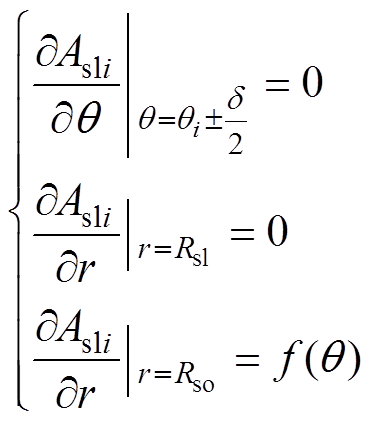 (18)
(18)
其中
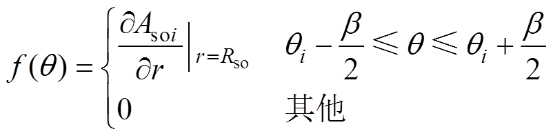 (19)
(19)
为了简化方程解的表达式,本文定义一组内置函数[8]为
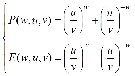 (20)
(20)
针对永磁体子域建立的泊松方程,其Arj的解[8]为
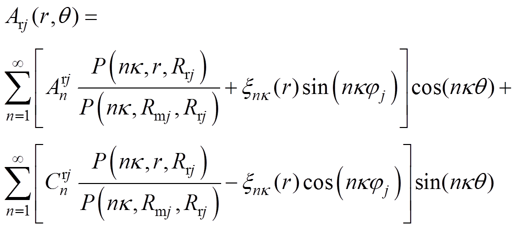 (21)
(21)
其中
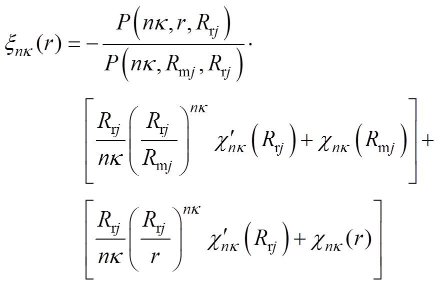 (22)
(22)
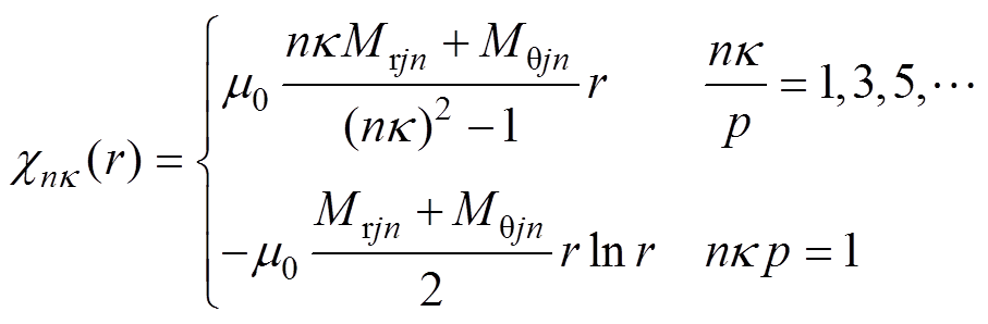 (23)
(23)
式中, 和
和 为永磁体域第j段磁极n阶谐波系数。
在气隙子域中建立的拉普拉斯方程,其Aair的解[8]为
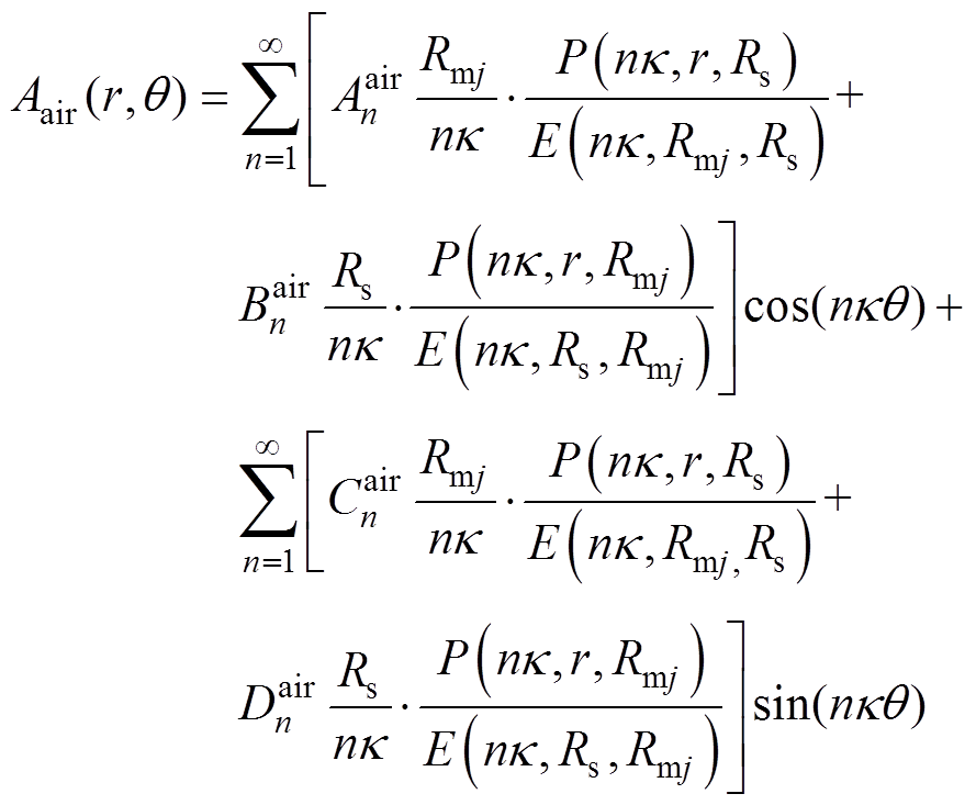 (24)
(24)
式中, 、
、 、
、 和
和 为气隙子域n阶谐波系数。
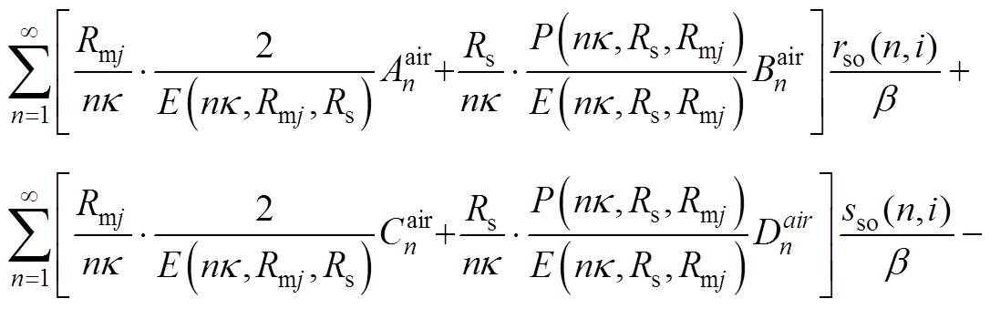
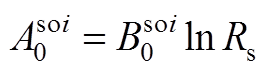
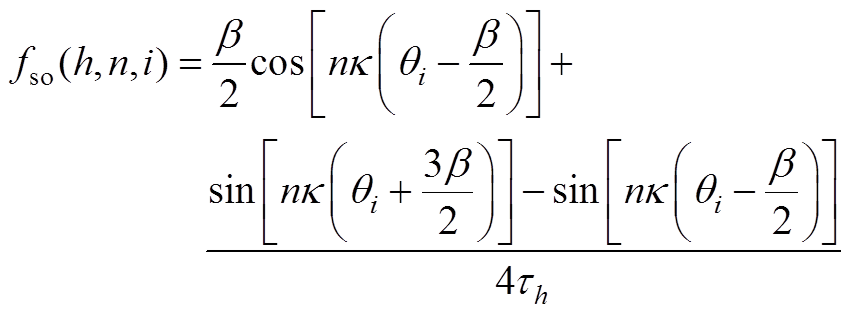
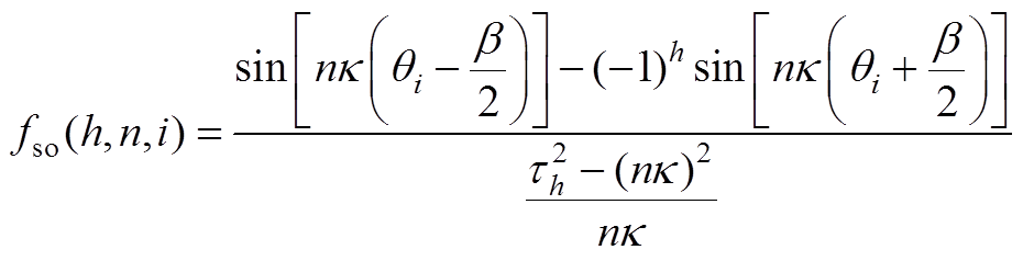
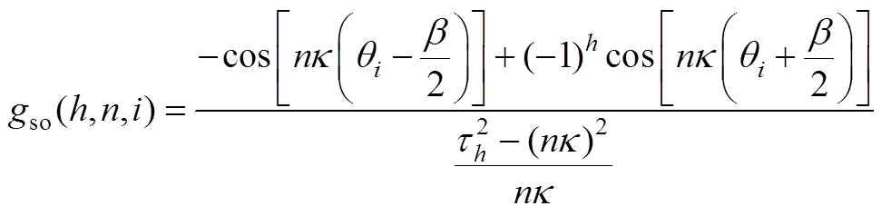
在槽开口区域建立的拉普拉斯方程,其Asoi的解[9]为
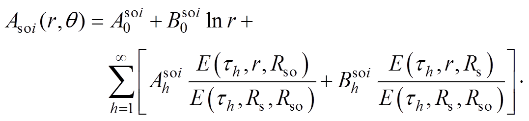
 (25)
(25)
式中, 和
和 为第i个槽开口域h阶谐波系数。
对于在定子槽区域建立的泊松方程,其Asli的解[9]为
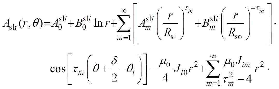
 (26)
(26)
其中
 (27)
(27)
式中, 和
和 为第i个定子槽域的m阶谐波系数。
通过相邻边界上边界条件求解的方程联立,建立各子域解中的谐波系数矩阵B为
 (28)
(28)
谐波系数有关方程参见附录,联立方程可得关于谐波系数的矩阵方程为
 (29)
(29)
其中
 (30)
(30)
 (31)
(31)
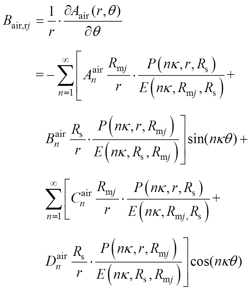
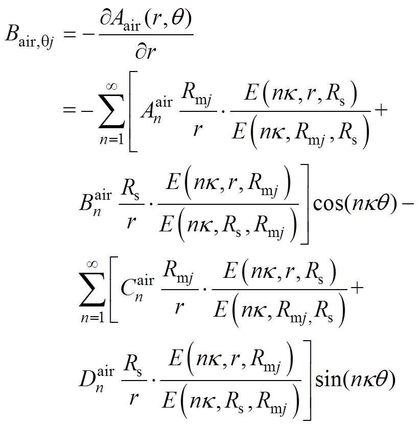
根据方程求得气隙子域的谐波系数,各分段磁极下气隙磁通密度的径向分量 和切向分量
和切向分量 分别为
分别为
 (32)
(32)
 (33)
(33)
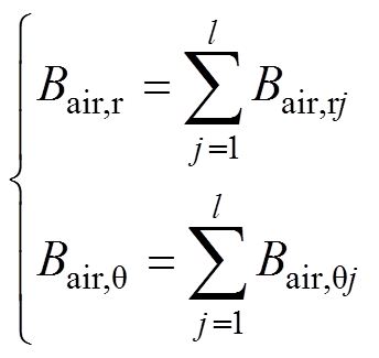
合成气隙磁通密度由各分段磁极气隙磁通密度叠加,其结果如图6所示,取磁极分段数为10段进行等效的结果。在各子域谐波阶数一定的情况下,磁极分段数越多,等效程度就越高,计算结果越精确。
 (34)
(34)
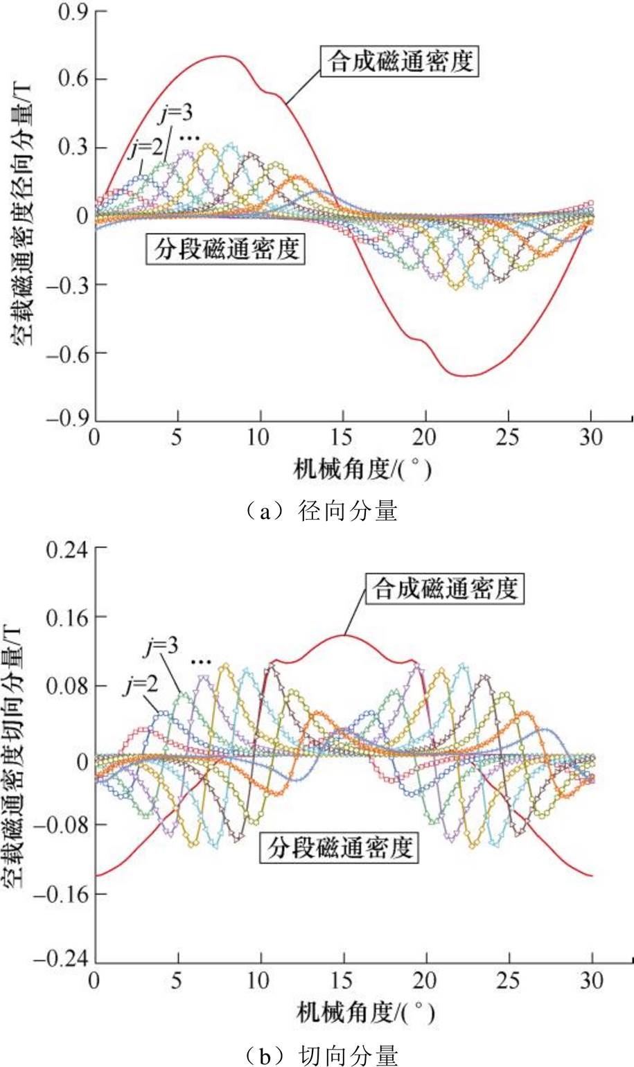
图6 合成磁通密度解析解
Fig.6 Analytical solution of synthetic flux density
为验证解析法的适用性与正确性,基于本文对不均匀气隙转子建模过程,表1给出了36槽24极偏心式和面包型磁极转子电机结构参数。
表1 电机结构主要参数
Tab.1 Main parameters of motor structure
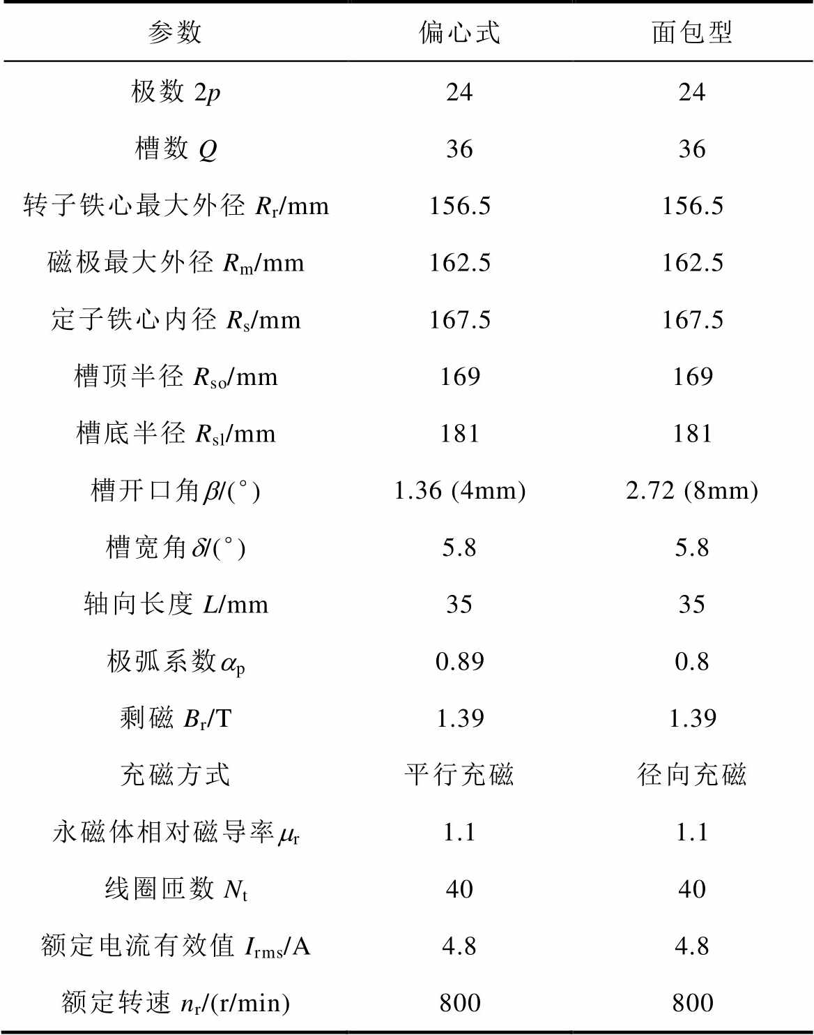
参数偏心式面包型 极数2p2424 槽数Q3636 转子铁心最大外径Rr/mm156.5156.5 磁极最大外径Rm/mm162.5162.5 定子铁心内径Rs/mm167.5167.5 槽顶半径Rso/mm169169 槽底半径Rsl/mm181181 槽开口角b/(°)1.36 (4mm)2.72 (8mm) 槽宽角d/(°)5.85.8 轴向长度L/mm3535 极弧系数ap0.890.8 剩磁Br/T1.391.39 充磁方式平行充磁径向充磁 永磁体相对磁导率mr1.11.1 线圈匝数Nt4040 额定电流有效值Irms/A4.84.8 额定转速nr/(r/min)800800
根据微积分原理对永磁体进行等极弧分段,最后电机二维气隙磁场可等效为每段磁极产生的磁场叠加效果总和,取气隙中间位置Re处r=Re= (Rm+Rs)/2的磁场结果。
图7~图9分别给出两种结构的空载、电枢反应以及负载工况下一对极结构的气隙磁通密度径向和切向分量计算结果,可以看出,解析法计算结果和有限元仿真结果虽存在误差,但整体吻合性较好。根据图8结果可知,由于此电机结构最小气隙长度为5mm,电枢反应下气隙磁通密度幅值小于0.02T,所以负载和空载下磁通密度波形结果较为接近;由于面包型结果是在偏心式基础上只改变槽开口宽、极弧系数和充磁方式后作为对比,两者结果波形相近,但实际面包型磁钢略厚以及槽开口更宽,所以其磁通密度幅值略高,开槽影响也较大。
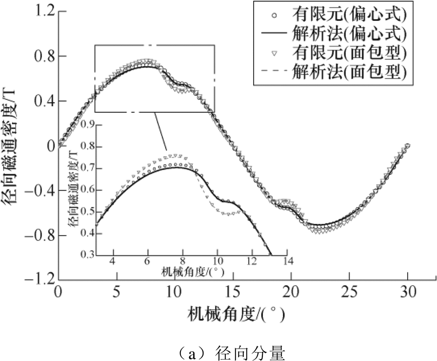
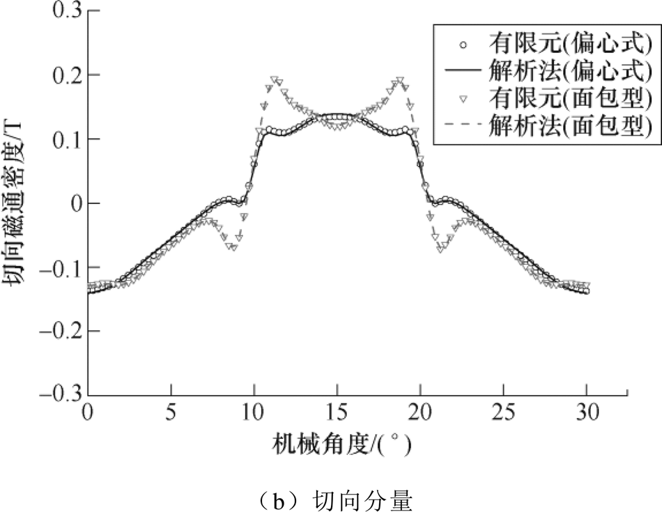
图7 空载气隙磁通密度
Fig.7 No-load air gap flux density
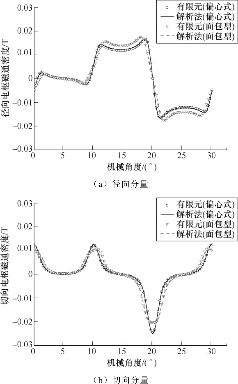
图8 电枢反应气隙磁通密度
Fig.8 Armature reaction air gap flux density
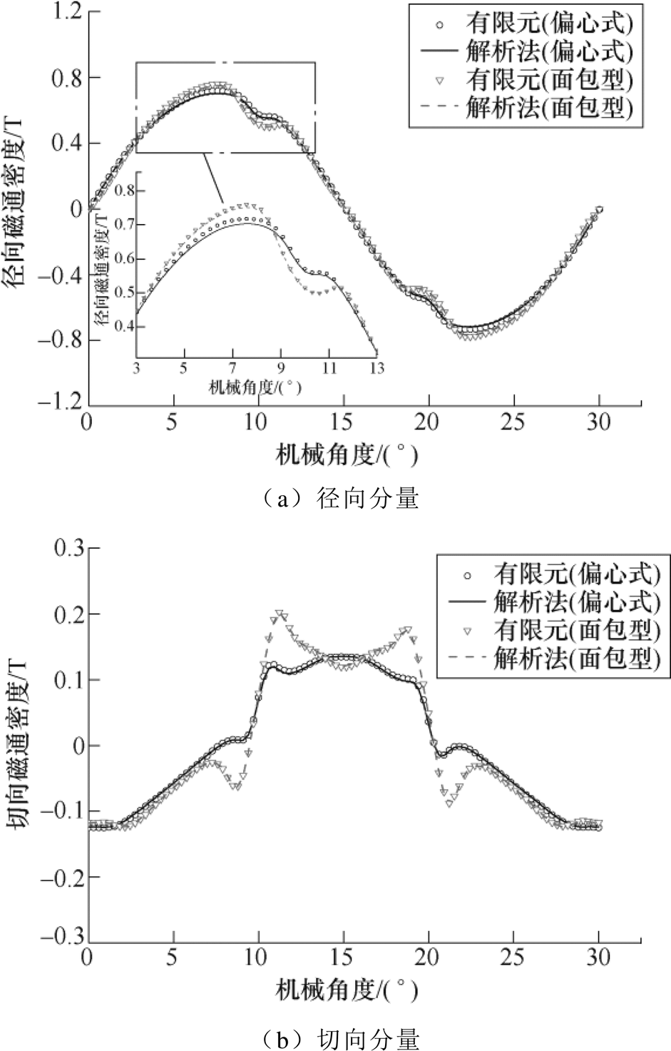
图9 负载气隙磁通密度
Fig.9 On-load air gap flux density
根据麦克斯韦张量法对齿槽转矩和电磁转矩进行计算,本文计算单元电机(2极3槽)下转矩结果,其积分路径为 ,转矩为
,转矩为
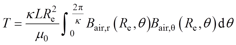 (35)
(35)
转矩结果如图10所示。由于面包型电机结构槽开口宽度增加为偏心式的2倍,极弧系数降低为0.8,齿槽转矩明显增大,其峰值为0.81N·m,偏心式为0.1N·m,其电磁转矩均值都在15N·m左右,解析结果和有限元结果对比下,两种结构波形变化趋势基本一致,面包型齿槽转矩有限元结果略高于解析结果。
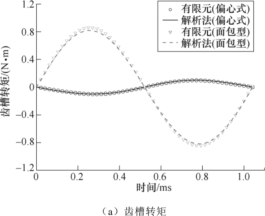
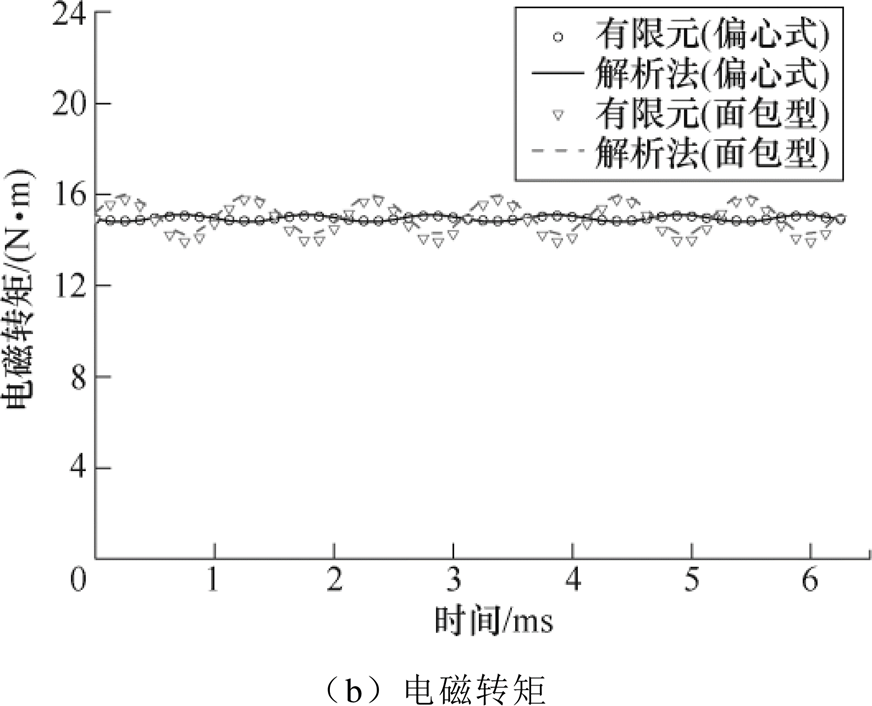
图10 转矩结果
Fig.10 Torque results
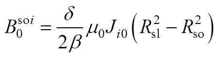
电机空载下,各相磁链和反电动势可由每槽线圈边的磁位差计算得出,即
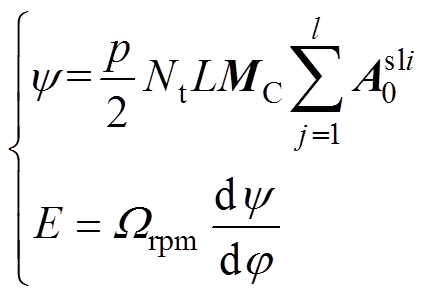 (36)
(36)
式中,Nt为线圈匝数;L为轴向长度; 为每小段磁极下定子槽开口域谐波系数;
 为电机转速。
图11给出了偏心式磁极电机其中一相的空载反电动势波形,峰值在140V,解析结果与有限元吻合较好。
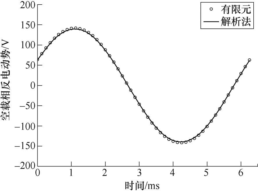
图11 空载相反电动势
Fig.11 Phase back EMF of no-load condition
研制了一台24极36槽平行充磁偏心式磁极转子的样机,以实验验证本文解析方法的准确性。通过示波器(每格100V)测得额定空载转速下线反电动势波形如图12所示,实验测得线反电动势峰值为242V,根据图13取一个电周期空载线反电动势对比,由于实测结果采样点较高以及可能存在其他影响因素,波形存在畸变,但整体上有限元、解析和实验结果数值和波形趋势高度吻合。
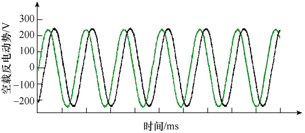
图12 实测空载线反电动势
Fig.12 Measured no load line back EMF
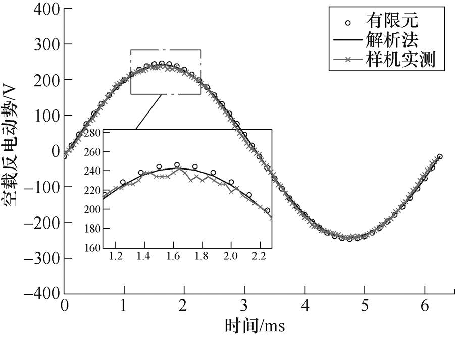
图13 空载线反电动势对比
Fig.13 Comparison of no load line back EMF
本文基于精确子域模型建立了面包型和偏心削极等特殊磁钢形状引起不均匀气隙的表贴式永磁同步电机空载磁场、电枢磁场和负载磁场分布的通用解析方法,同时考虑了径向/平行充磁,半闭口槽的任意单元电机模型以及传统均匀气隙表贴式结构。通过计算电机空载磁场、电枢磁场和负载磁场下的气隙磁通密度分布,验证了通用解析方法的准确性。在此基础上,计算了电机的齿槽转矩、电磁转矩及反向感应电动势,与有限元法的结果均吻合较好,研制的24极36槽偏心式磁极永磁同步电机实测反电动势波形与仿真结果吻合很好,验证了本文解析方法的正确性,为进一步优化该类电机的电磁性能奠定了良好的基础。
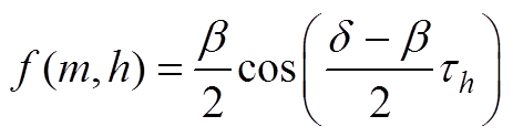
第j段磁极的磁化强度分量表示为
1)径向磁化
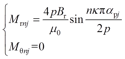 (A1)
(A1)
2)平行磁化
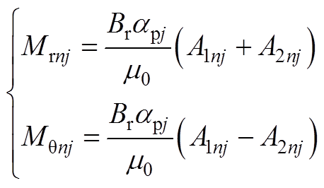 (A2)
(A2)
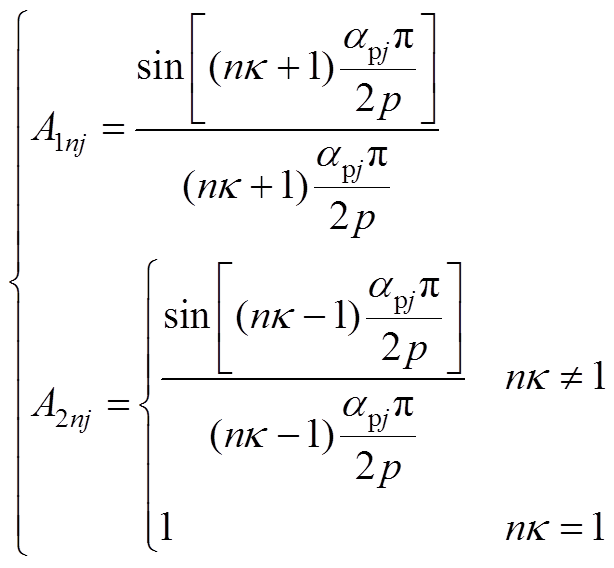 (A3)
(A3)
永磁体的磁化强度可表示为
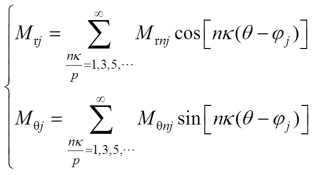 (A4)
(A4)
式中, 为永磁体N极中心位置角;Mrj和Mqj为第j段永磁体剩余磁化强度的径向分量和切向分量。
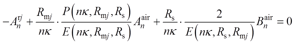
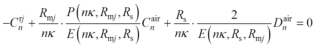
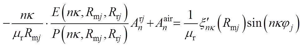
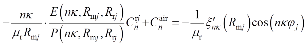
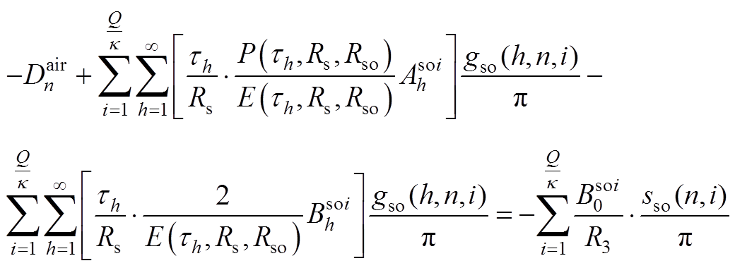
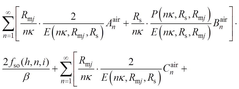
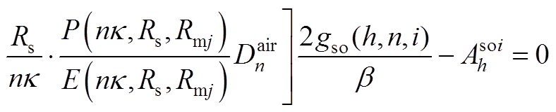
根据各子域偏微分方程基础解式(20)~式(27),通过各子域间边界条件式(14)~式(19),得到下面求解方程,通过将方程联立求得各子域谐波系数矩阵,然后进行电机性能参数求解。
 (A5)
(A5)
 (A6)
(A6)
 (A7)
(A7)
 (A8)
(A8)
 (A9)
(A9)
 (A10)
(A10)
 (A11)
(A11)
 (A12)
(A12)
 (A13)
(A13)
 (A14)
(A14)
 (A15)
(A15)
其中
 (A16)
(A16)
 (A17)
(A17)
 (A18)
(A18)
 (A19)
(A19)
当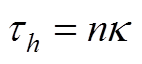 时
时
 (A20)
(A20)
 (A21)
(A21)
当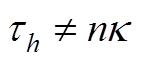 时
时
 (A22)
(A22)
 (A23)
(A23)
当 时
时
 (A24)
(A24)
当 时
时
 (A25)
(A25)
参考文献
[1] Zhu Ziqiang, Wu Lijian, Xia Zhenping. An accurate subdomain model for magnetic field computation in slotted surface-mounted permanent-magnet machines[J]. IEEE Transactions on Magnetics, 2010, 46(4): 1100- 1115.
[2] Wu Lijian, Zhu Ziqiang, Staton D, et al. An improved subdomain model for predicting magnetic field of surface-mounted permanent magnet machines accounting for tooth-tips[J]. IEEE Transactions on Magnetics, 2011, 47(6): 1693-1704.
[3] Rahideh A, Korakianitis T. Analytical magnetic field distribution of slotless brushless machines with inset permanent magnets[J]. IEEE Transactions on Mag- netics, 2011, 47(6): 1763-1774.
[4] Rahideh A, Korakianitis T. Analytical armature reaction field distribution of slotless brushless machines with inset permanent magnets[J]. IEEE Transactions on Magnetics, 2012, 48(7): 2178-2191.
[5] Rahideh A, Korakianitis T. Analytical magnetic field calculation of slotted brushless permanent-magnet machines with surface inset magnets[J]. IEEE Transa- ctions on Magnetics, 2012, 48(10): 2633-2649.
[6] Rahideh A, Mardaneh M, Korakianitis T. Analytical 2-D calculations of torque, inductance, and back-EMF for brushless slotless machines with surface inset magnets[J]. IEEE Transactions on Magnetics, 2013, 49(8): 4873-4884.
[7] Lubin T, Mezani S, Rezzoug A. 2-D exact analytical model for surface-mounted permanent-magnet motors with semi-closed slots[J]. IEEE Transactions on Magnetics, 2011, 47(2): 479-492.
[8] Lubin T, Mezani S, Rezzoug A. Two-dimensional analytical calculation of magnetic field and electro- magnetic torque for surface-inset permanent-magnet motors[J]. IEEE Transactions on Magnetics, 2012, 48(6): 2080-2091.
[9] 张凤阁, 陈进华, 刘光伟, 等. 面贴式异向旋转双转子永磁电机的磁场解析计算[J]. 电工技术学报, 2011, 26(12): 28-36.
Zhang Fengge, Chen Jinhua, Liu Guangwei, et al. Analytical solution of magnetic field for surface- mounted permanent magnet machines with anti- rotation dual rotors[J]. Transaction of China Electro- technical Society, 2011, 26(12): 28-36.
[10] 李琛, 章跃进, 仇志坚. 无轴承交替极永磁电机空载气隙磁场全局解析模型[J]. 电工技术学报, 2012, 27(11): 104-110.
Li Chen, Zhang Yuejin, Qiu Zhijian, et al. Exact analytical model for the no-load air-gap magnetic field calcution in consequent-pole permanent magnet bearingless motor[J]. Transaction of China Electro- technical Society, 2012, 27(11): 104-110.
[11] 郭思源, 周理兵, 曲荣海, 等. 基于精确子域模型的游标永磁电机解析磁场计算[J]. 中国电机工程学报, 2013, 33(30): 71-80.
Guo Siyuan, Zhou Libing, Qu Ronghai, et al. Analy- tical magnetic field calcution of vernier permanent- magnet machines based on accurate subdomain model[J]. Proceedings of the CSEE, 2013, 33(30): 71-80.
[12] 张守首, 郭思源. 考虑分段斜极和磁性槽楔的永磁同步电机磁场解析方法[J]. 电工技术学报, 2019, 34(1): 11-22.
Zhang Shoushou, Guo Siyuan. Analytical magnetic field method of permanent magnet synchronous machine considering step-skewed magnets and mag- netic slot wedge[J]. Transaction of China Electro- technical Society, 2019, 34(1): 11-22.
[13] 李灏淳, 李立毅, 于吉坤, 等. 多边形转子磁轭永磁同步电机空载气隙磁场解析计算[J]. 中国电机工程学报, 2018, 38(11): 3354-3364.
Li Haochun, Li Liyi, Yu Jikun, et al. Analytic calculation of no-load air-gap magnetic fields of polygonal rotor magnetic yoke permanent magnet synchronous motors[J]. Proceedings of the CSEE, 2018, 38(11): 3354-3364.
[14] 胡鹏飞, 王东, 靳栓宝, 等. 偏心磁极永磁电机气隙磁场正弦优化模型[J]. 电工技术学报, 2019, 34(18): 3759-3768.
Hu Pengfei, Wang Dong, Jin Shuanbao, et al. Sinusoidal optimization model for air gap magnetic field of eccentric magnetic pole permanent magnet motor[J]. Transaction of China Electrotechnical Society, 2019, 34(18): 3759-3768.
[15] 倪有源, 王磊, 王群京. 凸形不等厚磁极永磁电机建模与分析[J]. 电工技术学报, 2020, 35(11): 2406- 2414.
Ni Youyuan, Wang Lei, Wang Qunjing. Modeling and analysis of permanent magnet machines with salient shape unequal thickness magnets[J]. Transaction of China Electrotechnical Society, 2020, 35(11): 2406- 2414.
[16] Zhou Yu, Li Huaishu, Meng Guangwei, et al. Analytical calculation of magnetic field and cogging torque in surface-mounted permanent-magnet machines accounting for any eccentric rotor shape[J]. IEEE Transactions on Industrial Electronics, 2015, 62(6): 3438-3447.
[17] 赵国新, 张宇, 葛红岩, 等. 偏心磁极永磁电机气隙磁密解析计算方法研究[J]. 电机与控制学报, 2020, 24(6): 24-32.
Zhao Guoxin, Zhang Yu, Ge Hongyan, et al. Prediction of flux density distribution inpermanent magnet motor with eccentric magnetic pole[J]. Electric Machine and Control, 2020, 24(6): 24-32.
[18] Wu Lijian, Zhu Ziqiang. Analytical modeling of surface-mounted PM machines accounting for magnet shaping and varied magnet property distribution[J]. IEEE Transactions on Magnetics, 2014, 50(7): 1-11.
[19] 于占洋, 李岩, 井永腾, 等. 基于混合磁场解析法的磁极偏心型表贴式永磁同步电机空载特性分析[J]. 电工技术学报, 2020, 35(18): 3811-3820.
Yu Zhanyang, Li Yan, Jing Yongteng, et al. No-load characteristic analysis of surface-mounted permanent magnet synchronous motor with non-concentric pole based on hybrid magnetic field analysis method[J]. Transaction of China Electrotechnical Society, 2020, 35(18): 3811-3820.
Analytical Calculation of Magnetic Field of Permanent Magnet Synchronous Motor with Uneven Air Gap Structure
Abstract In order to achieve sinusoidal back EMF and low torque ripple in the design process of permanent magnet motor for industrial robot and numerical control machine, the uneven air gap structure of bread-shaped or eccentric pole cutting is often used. Based on the differential principle, the rotor pole of the non-uniform air gap structure was divided into four subdomains: permanent magnet, air gap, slot opening and stator slot, and the Poisson equation and Laplace equation were established. The partial differential equation was solved by the variable separation method and the Fourier series method. The harmonic coefficients of each subdomain were solved by the boundary conditions to obtain the magnetic field distribution of each segmented pole, and then the two-dimensional magnetic field distribution of the electric machine was obtained by the equivalent superposition based on the integral principle. The analytical method also takes into account the pole rotor structure of tile type, eccentric type and bread type, and can calculate the no-load, armature and load magnetic field characteristics of the motor with any number of units. Accordingly, the torque and no-load back EMF characteristics can be calculated. The analytical method is verified by the comparison of the prototype test results, the finite element simulation results and the analytical results, which can quickly guide the motor design.
keywords:Permanent magnet synchronous motor, subdomain analysis method, uneven air gap, isopolar arc segmentation, magnetic field performance
DOI: 10.19595/j.cnki.1000-6753.tces.210299
中图分类号:TM315
国家自然科学基金青年科学基金(51807194)和宁波市科技创新2025重大专项(2019B10077, 2021Z125, 2018B10026)资助项目。
收稿日期 2021-03-11
改稿日期 2021-05-13
赵士豪 男,1996年生,硕士,研究方向为多相永磁电机设计与分析。E-mail: zhaoshihao@nimte.ac.cn
陈进华 男,1985年生,博士,正高级工程师,博士生导师,研究方向为特种永磁电机及其控制。E-mail: chenjinhua@nimte.ac.cn(通信作者)
(编辑 崔文静)