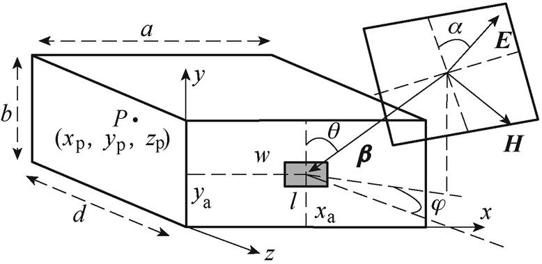
图1 平面波激励下的开孔有损屏蔽腔体
Fig.1 Geometry of a lossy shielding enclosure with apertures against an oblique incident plane wave
摘要 该文提出一种分析平面波照射下有损腔体屏蔽问题的解析模型,该模型不仅可以快速预测有损腔体偏心开孔和任意位置目标点时的屏蔽效能,而且还可以准确分析损耗导电材料对较高频率处高阶谐振模式的抑制效应。首先根据电磁拓扑理论和电路理论,构建有损屏蔽腔体的等效电路以及信号流图;其次通过信号流图建立广义BLT方程,并利用该方程计算目标点所在横截面的最大电压响应;最后根据电压和电场分布的关系,得到目标点处的总电场分量。该模型能够方便地处理单孔、孔阵及双面开孔有损腔体的情况,并通过全波仿真软件CST验证了其有效性和准确性,为分析有损腔体的屏蔽问题提供一种可靠高效的计算方法。
关键词:有损腔体 屏蔽效能 抑制效应 电磁拓扑理论 广义BLT方程
随着能源互联网、电力系统以及电网的不断发展[1-5],各种电气和电子设备日益遭受到电磁干扰的影响[6-7]。为了保证系统或设备的正常工作,往往会采用金属屏蔽腔体隔绝外界干扰源对内部器件的电磁耦合作用,从而起到保护的功能。金属腔体的性能一般利用屏蔽效能来衡量,然而由于腔体表面往往会开有不同类型的孔缝,这些孔缝不仅降低了金属腔体的屏蔽效果,而且还破坏了系统的屏蔽完整性[8-10]。一般情况下,研究金属腔体屏蔽问题的方法主要分为两大类:数值方法和解析方法。数值方法,如时域有限差分法[11-12]、传输线矩阵模型[13-14]和矩量法[15-16]等,具有计算准确、精度高的优势,但是这类方法往往需要对开孔金属腔体进行精确建模,从而占用大量的计算资源、花费大量的计算时间;解析方法,如M. P. Robinson等提出的等效电路法[17]、H. A. Bethe提出的小孔耦合理论[18]和多模中间级等效电路模型[19]等,具有建模简单、计算效率高以及方便分析参数影响等优势,在一定精度条件下可以快速分析开孔金属腔体的屏蔽问题。
近年来,在预测开孔金属腔体屏蔽效能和谐振模式的解析方法中,应用最为广泛的是等效电路方法和广义BLT(Baum-Liu-Tesche)方程。传统等效电路方法具有较多的限制条件、能够解决的情况较少,许多学者经过大量研究工作使其可以处理斜入射平面波、高阶模式、偏心开孔以及任意位置目标点等情况[20-22],极大地拓展了该方法的应用范围;虽然基于电磁拓扑理论的广义BLT方程在分析开孔金属腔体屏蔽问题时具有更高的计算效率和精度,但是一些研究工作在应用该方程时却局限于一些限制条件,例如,文献[23]只能处理中心开孔及目标点在腔体中心位置的情况;文献[24]在低频率时才能计算得到较为准确的屏蔽效能结果;文献[25]没有考虑矩形波导中的横磁传播模式,导致一些算例的计算误差较大且一些谐振模式不能被预测。
通常情况下,绝大多数文献在研究屏蔽问题时都假设腔体由理想导体材料组成[26-27]。事实上,当腔体由损耗导电材料构成时,会对屏蔽效能和谐振模式产生较大影响,而这方面的研究较少。虽然文献[28]基于传输线理论和波导理论,利用等效电路法计算了中等导电材料覆盖腔体前壁时的屏蔽效能,但是考虑的情况并不能算真正意义上的有损腔体且不能分析开孔腔体的屏蔽问题。文献[29]考虑了一种内壁覆盖有导电材料的开孔屏蔽腔体,并利用拓展的等效电路方法分析了腔体侧壁损耗对谐振效应的抑制作用。然而,该拓展的电路方法只考虑了主模的影响,因此无法预测有损腔体在较高频域范围时的屏蔽效能和高阶谐振模式。
本文结合电磁拓扑理论和有损矩形波导的传播常数,提出了一种可以快速预测有损腔体屏蔽效能和谐振模式的解析模型。首先根据电路理论和电磁拓扑理论,建立平面波照射下有损屏蔽腔体的等效电路以及信号流图;其次利用广义BLT方程计算目标点所在横截面的最大电压响应;最后根据电压响应和电场分布的关系,计算得到目标点处的电场总分量,从而计算得到腔体内部目标点处的屏蔽效能。本文模型可以准确地解决有损腔体偏心开孔、任意目标点及多种传播模式时的情况;此外,由于广义BLT方程中的开孔散射矩阵能够考虑孔缝和腔体之间的双向能量流动,因此可以方便地处理双面开孔有损腔体的屏蔽问题。将本文模型的计算结果与全波仿真软件CST的计算结果进行对比,验证了该模型的有效性和高效性。
平面波激励下的开孔有损屏蔽腔体如图1所示,平面波激励下有损屏蔽腔体的尺寸为a´b´d,腔体厚度为t;腔体前壁上矩形开孔的尺寸为l´w,其在xOy平面的中心点坐标为(xa, ya);腔体内部目标点P的坐标为(xp, yp, zp),并定义外界平面波的极化角为a,方位角为j,仰角为q。
根据矢量分解方法[20],平面波的矢量电场可以分解为
图1 平面波激励下的开孔有损屏蔽腔体
Fig.1 Geometry of a lossy shielding enclosure with apertures against an oblique incident plane wave
 (1)
(1)
式中,E0为矢量电场E的幅值;H0=E0/Z0为矢量磁场H的幅值,Z0为自由空间的特征阻抗,Z0≈377W;Fpx、Fpy和Fpz为沿着坐标轴方向的电压分配系数;ex、ey和ez为坐标轴方向的单位矢量。
同理,矢量传播常量可以分解为

 (2)
(2)
式中,b0为矢量传播常量b 的幅值;Fix、Fiy和Fiz为沿着坐标轴方向的传播常量分配系数。
有损屏蔽腔体上开孔的等效阻抗为
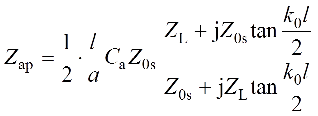 (3)
(3)其中
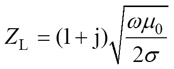
式中, 为开孔的耦合系数[21];m和n为模式指数;k0为自由空间的波数;l 为平面波的波长;
 为开孔有损屏蔽腔体阻抗;m0和s 分别为导电材料的磁导率和电导率。
 (4)
(4)
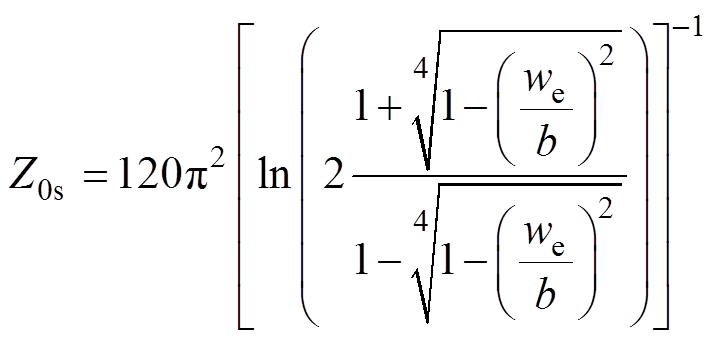
 (5)
(5)式中,we为开孔的有效宽度。
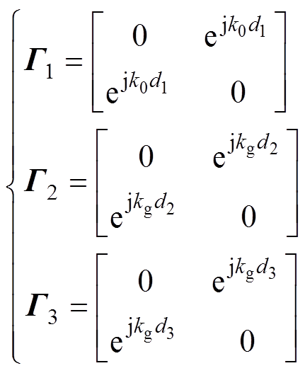
外界平面波激励下开孔有损屏蔽腔体的等效电路如图2所示。在等效电路中,平面波等效为电压源V0,二端口网络[S]ap表示开孔;Zg和kg分别为有损矩形波导的特征阻抗和传播常数;d1为腔体外部监测点到开孔的距离,其中,电压源到监测点和开孔的距离分别为d11和d12;腔体中的目标点P到开孔和腔体底端的距离分别为d2和d3;Vp为目标点P所在横截面的最大电压响应。
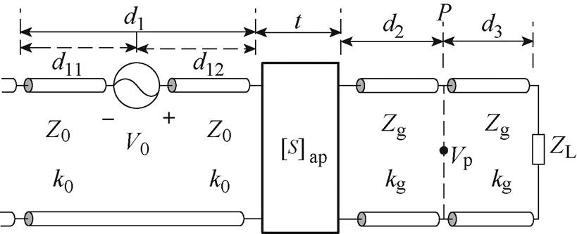
图2 平面波激励下开孔有损屏蔽腔体的等效电路
Fig.2 The equivalent circuit of the lossy shielding enclosure with an aperture
图3为屏蔽腔体等效电路的信号流图,其中,节点J1表示腔体外部监测点,J2表示开孔,J3表示腔体内部目标点P,J4表示腔体末端;管道T1表示电磁能量在腔体外部自由空间的传播,管道T2和T3表示电磁能量在腔体内部空间的传播; 和
和 (i和j分别表示管道和节点序号)分别表示节点上传播的入射电压波和反射电压波。
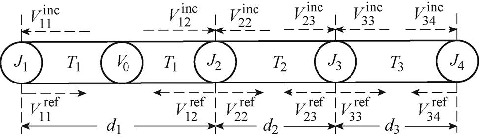
图3 屏蔽腔体等效电路的信号流图
Fig.3 The signal flow graph for the equivalent circuit model for the shielding enclosure
信号流图中节点处的电压响应可以通过广义BLT方程计算得到
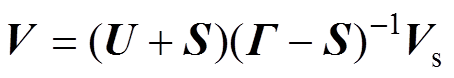 (6)
(6)其中
V=[V11 V12 V22 V23 V33 V34]T
S=[ r1 S2 S3 r4]T
G =[G1 G2 G3]T
式中,V为节点处的未知电压响应;U为单位矩阵;S为节点处的散射矩阵;G 为管道的传播矩阵;激励源矢量为
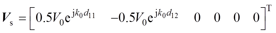 (7)
(7)节点J1和J4的反射系数分别为r1=0和r4= (ZL-Zg)/(ZL+Zg),节点J2和J3的散射矩阵分别为
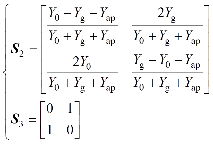 (8)
(8)
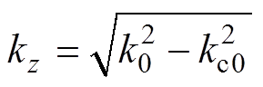
式中,Y0、Yg和Yap分别为自由空间、有损矩形波导和开孔的特征导纳; 为有损矩形波导中TE传播模式的特征阻抗,=Z0k0/kg,其中,kg=-jg,且参数g [29]满足
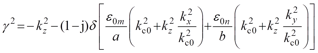 (9)
(9)其中
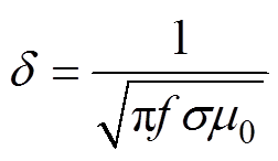
式中,kz和kc0分别为矩形波导的相位常数和截止波数;e0m和e0n为诺黎曼系数,当m(n)=0时,e0m(n)=1,当m(n)≠0时,e0m(n)=2; 为损耗导电材料的趋肤深度。
各个管道的传播矩阵分别为
 (10)
(10)有损矩形腔体波导中存在多种传播模式,根据电压响应和电场分布的关系[30],可以得到TE模式时目标点P处的电场分量为
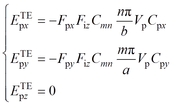 (11)
(11)
式中,模式指数m不能为零; 为归一化常数,
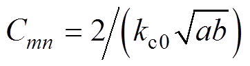 ;目标点的横向位置系数为
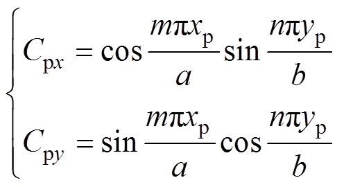 (12)
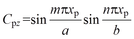
(12)同理,可以得到TM模式时目标点P处的电场分量为
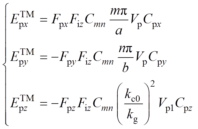 (13)
(13)
式中,模式指数m和n不能为零;Vp1为TM模式时目标点P处的最大电压响应,此时波导的特征阻抗为 =Z0kg/k0;目标点P处的纵向位置系数为
结合式(11)和式(13)可以得到目标点P在不同坐标轴方向的电场总分量为
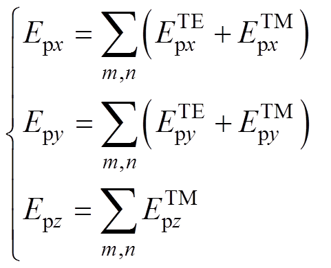 (14)
(14)最后,目标点P点处的屏蔽效能可以表示为
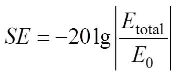 (15)
(15)
其中
 (16)
(16)假设屏蔽腔体尺寸为300mm´120mm´260mm,腔体厚度为1mm,损耗导电材料的电导率为104S/m;平面波角度分别设置为j =0°、q =90°和a =0°,分析的频域范围为0.3~2.4GHz。表1首先设置了6组仿真算例,考虑的3个参数分别为开孔尺寸、开孔中心点坐标以及目标点坐标。
表1 仿真算例1~6的参数设置
Tab.1 Parameter settings of the cases 1~6

算例开孔尺寸/(mm×mm)开孔中心点坐标/mm目标点坐标/mm 140´20(150, 60)(150, 60, -215) 240´20(150, 60)(245, 85, -215) 340´20(100, 30)(65, 100, -90) 440´20(55, 85)(55, 85, -135) 520(直径)(150, 60)(66, 29, -215) 620´20(64, 68)(66, 29, -215)
算例1和2考虑的是中心开孔情况,其中,算例1的目标点位于腔体中轴线上,而算例2的目标点位于腔体内部右上角区域。图4a给出了算例1时本文模型、拓展电路方法[29]和CST的计算结果对比,而图4b描述的则是算例2时本文模型计算得到的屏蔽效能结果与CST的计算结果对比。从两张图中可以看到:①本文模型和CST的计算结果有很好的一致性,验证了本文模型预测有损腔体屏蔽效能和谐振模式的有效性;②拓展电路方法的计算结果与CST的计算结果差距较大,尤其是1.5GHz以后计算误差逐渐增大,并且不能准确地预测高频处的高阶谐振模式。
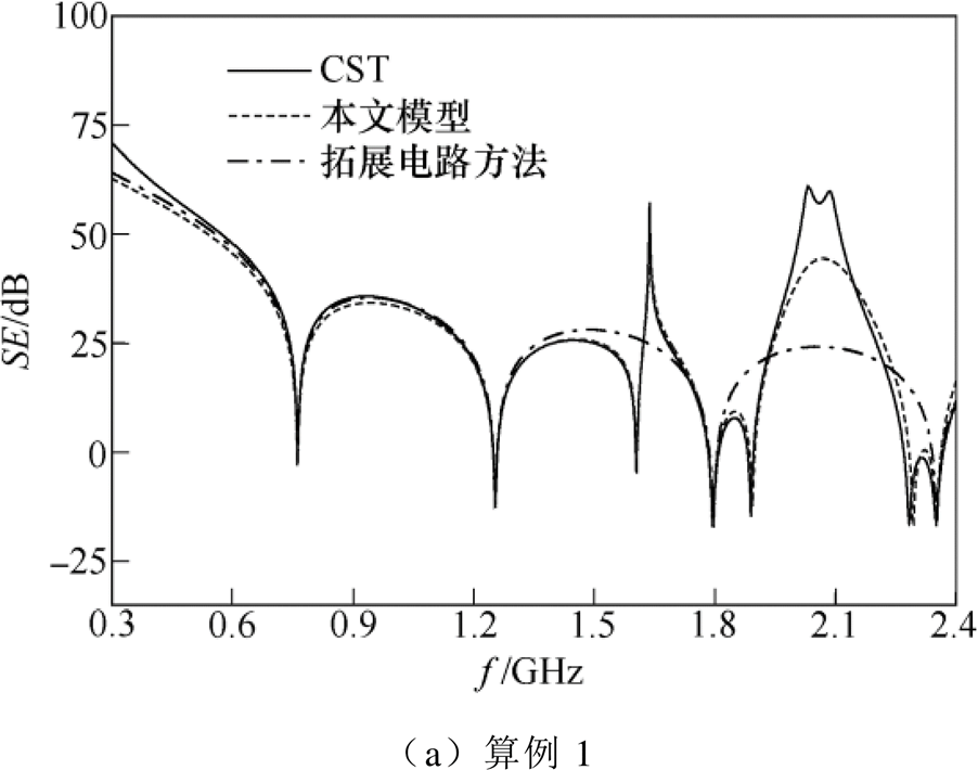
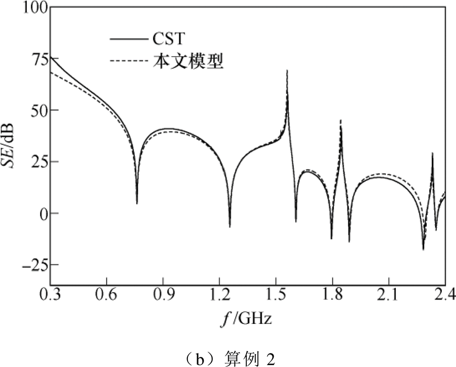
图4 中心开孔时本文模型(拓展电路方法)与 CST计算得到的屏蔽效能结果对比
Fig.4 Comparison of the SE results of the centered apertures obtained by the presented model (extended circuit method) and CST simulation
算例3和算例4考虑的是偏心开孔的情况,其中,算例3的目标点位于腔体内部左上角区域,而算例4的目标点位于开孔中轴线上。图5a和图5b分别给出了算例3和4时本文模型与CST计算得到的屏蔽效能结果对比,从图中可以看到,两种方法的计算结果有很好的一致性,验证了本文模型可以有效地处理偏心开孔时的有损屏蔽腔体。此外,相比于中心开孔的情况,偏心开孔时可以激发出更多的谐振模式,这是由于中心开孔位于腔体对称位置,此时目标点处的电场分布存在比较严重的相互抵消现象,导致一些谐振模式不能被激发。
算例1~4考虑的为单个开孔的情况,而算例5和6考虑的则是圆形孔阵和方形孔阵的情况,其中,算例5的孔阵中心点位于腔体前壁中心位置,而算例6的孔阵中心点位于前壁左侧位置。图6a和图6b分别给出了圆形孔阵和方形孔阵时本文模型和CST的屏蔽效能计算结果对比,从图中可以看到,两种方法计算得到的屏蔽效能结果符合得很好,验证了本文模型在预测开有孔阵的有损腔体屏蔽效能和谐振模式时的有效性和准确性。
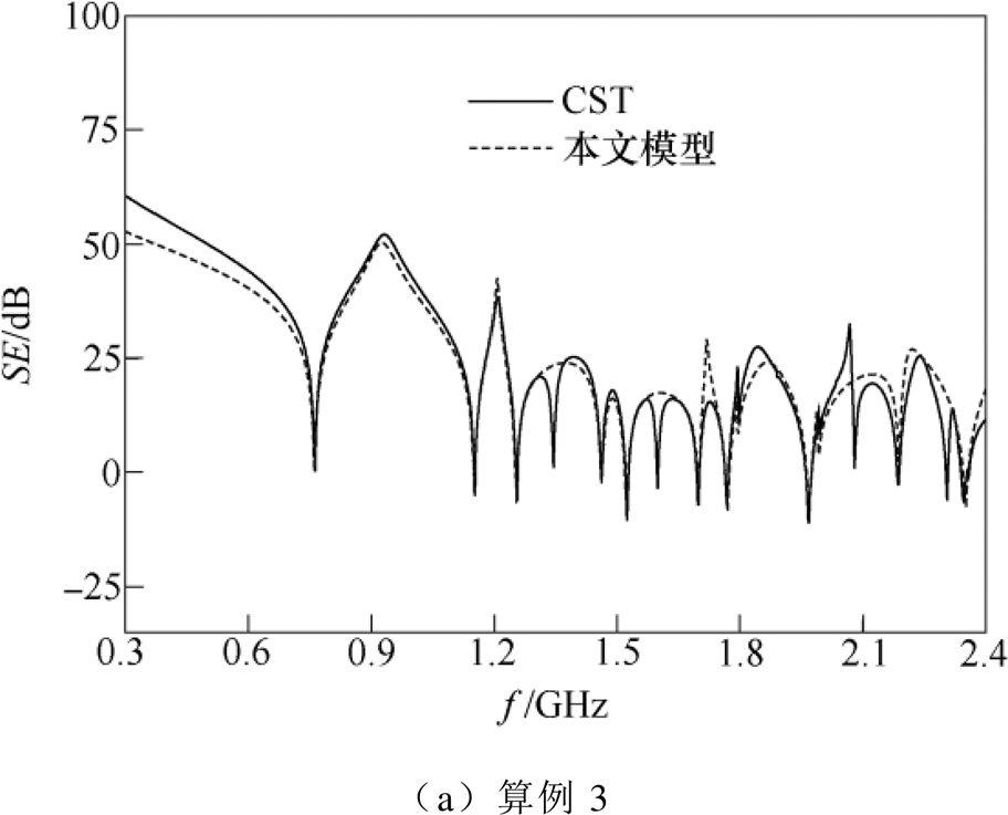
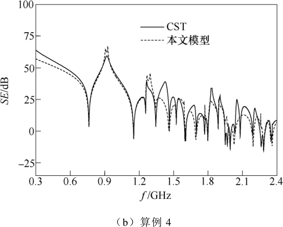
图5 偏心开孔时本文模型与CST计算得到的屏蔽效能结果对比
Fig.5 Comparison of the SE results of the off-centered apertures obtained by the presented model and CST simulation
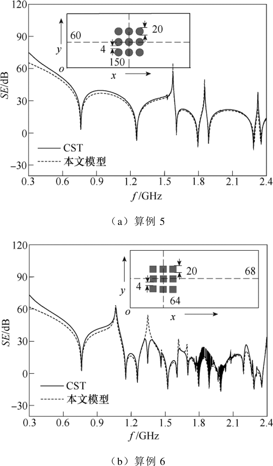
图6 圆形孔阵和方形孔阵时本文模型与CST计算得到的屏蔽效能结果对比
Fig.6 Comparison of the SE results of the aperture arrays obtained by the presented model and CST simulation
接下来考虑双面开孔有损屏蔽腔体的情况,假设屏蔽腔体的尺寸为300mm´120mm´300mm,并设置算例7和8验证本文模型的有效性。算例7时腔体的正面和背面都为单个中心开孔,开孔的尺寸为30mm´12mm;算例8时腔体的正面和背面都为方形孔阵,单个方形开孔的边长为20mm。图7a和图7b分别给出了双面开孔算例7和8时本文模型与CST计算得到的屏蔽效能结果对比,从图中可以看出,本文模型和CST的屏蔽效能计算结果有很好的一致性,验证了本文方法在预测双面开孔屏蔽问题时的有效性。事实上,通过本文模型可以方便地处理双面开孔的情况,这是因为利用开孔的散射矩阵不仅可以考虑腔体外部耦合到内部的能量,还可以考虑腔体内部泄漏到外部的能量。
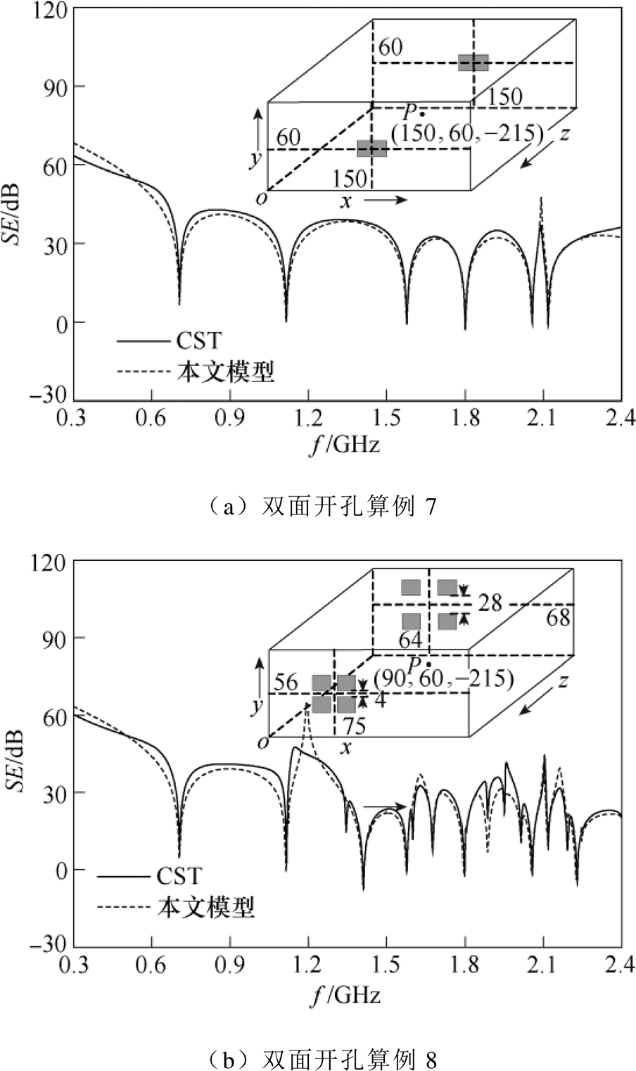
图7 双面开孔有损腔体时本文模型与CST计算得到的屏蔽效能结果对比
Fig.7 Comparison of the SE results for a lossy enclosure with apertures at two opposing walls obtained by the presented model and CST simulation
文献[29]在0.4~0.9GHz频域范围内讨论了腔体壁损耗对低阶谐振模式的抑制作用。为了进一步研究有损腔体对较高频率处高阶模式的抑制作用,基于表1中的算例5和6,图8a和图8b分别给出了腔体材料电导率为3.54´107S/m时本文模型与CST的屏蔽效能计算结果对比,从图中可以看出,两种方法计算得到的结果同样有很好的一致性。
图9给出了两种不同电导率(3.54´107S/m和104S/m)时本文模型得到的屏蔽效能计算结果对比,从图中可以观察到,有损腔体对整个频域段的谐振模式都有明显的抑制作用,包括较高频域段的高阶谐振模式,并且损耗导电材料的电导率越小,对谐振模式的抑制作用越强,谐振点附近的屏蔽效能数值越大。为了定量说明有损腔体对谐振模式的抑制作用,表2分别给出了两种不同电导率时3个谐振点处(f =0.71GHz、1.12GHz和1.58GHz)的屏蔽效能数值,可以看到,电导率为104S/m时的屏蔽效能明显大于电导率为3.54´107S/m时的。
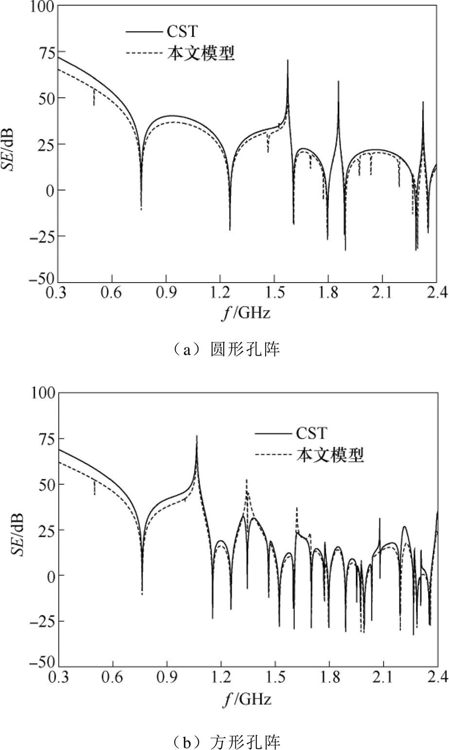
图8 孔阵情况时本文模型与CST计算得到的屏蔽效能结果对比(电导率为3.54´107S/m)
Fig.8 Comparison of the SE results for the aperture arrays obtained by the presented model and CST simulation (the conductivity is 3.54´107S/m)
表2 两种不同电导率时3个谐振点处的屏蔽效能数值
Tab.2 The SE values at three resonance points for two different conductivities
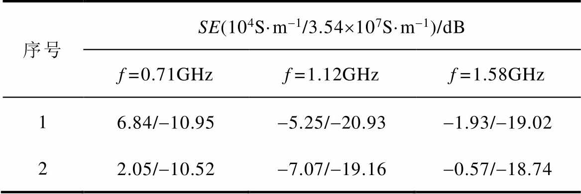
序号SE(104S·m-1/3.54´107S·m-1)/dB f=0.71GHzf=1.12GHzf=1.58GHz 16.84/-10.95-5.25/-20.93-1.93/-19.02 22.05/-10.52-7.07/-19.16-0.57/-18.74
本文模型在预测开孔有损腔体的屏蔽效能和谐振模式时具有很高的计算精度和计算效率。所有算例都在同一计算机上完成,算例的仿真环境为Intel® Xeon® E5-4607v2 @2.6GHz CPU,64G内存,其中,CST完成计算大约需要几个小时,而本文模型完成计算所需要的时间不超过25s,充分说明了该方法的高效性。
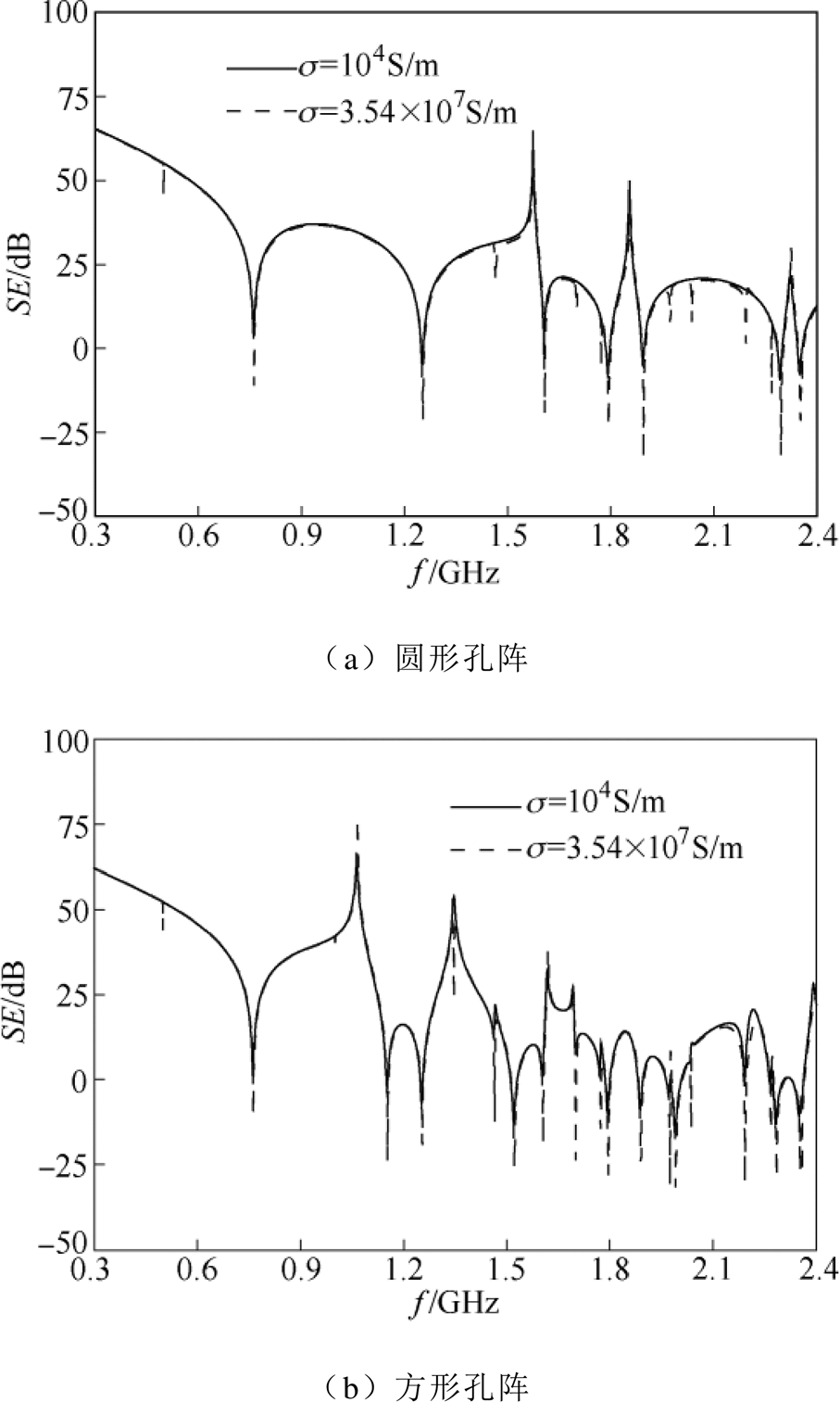
图9 两种电导率时本文模型计算得到的屏蔽效能对比
Fig.9 Comparison of the SE results obtained by the presented model for two different conductivities
本文基于电磁拓扑理论和有损矩形波导的传播常数,提出了一种快速预测有损腔体屏蔽效能和谐振模式的解析模型。利用该模型可以准确地处理偏心开孔、孔阵、任意目标点以及多种模式的情况;同时,由于该模型能够通过散射矩阵描述开孔内外的能量流动,因此可以方便地分析双面开孔有损腔体的屏蔽问题。将本文模型的计算结果与全波仿真软件CST的计算结果进行对比,验证了本文模型的有效性和高效性,结果表明,有损屏蔽腔体可以有效抑制整个频域范围内的谐振模式,包括较高频域处的高阶模式,能够显著提高谐振频点附近的屏蔽效能。本文模型为分析有损腔体的屏蔽问题提供了一种可靠和准确的计算方法,并为具有不同电导率开孔腔体的电磁屏蔽设计问题提供了参考。
参考文献
[1] 郭庆来, 王博弘, 田年丰, 等. 能源互联网数据交易: 架构与关键技术[J]. 电工技术学报, 2020, 35(11): 2285-2295.
Guo Qinglai, Wang Bohong, Tian Nianfeng, et al. Data transactions in energy internet: architecture and key technologies[J]. Transactions of China Electro- technical Society, 2020, 35(11): 2285-2295.
[2] 肖勇, 钱斌, 蔡梓文, 等. 电力互联网终端非法无线通信链路检测方法[J]. 电工技术学报, 2020, 35(11): 2319-2327.
Xiao Yong, Qian Bin, Cai Ziwen, et al. Malicious wireless communication link detection of power internet of thing devices[J]. Transactions of China Electrotechnical Society, 2020, 35(11): 2319-2327.
[3] 陈民权, 甘德强, 康卓然, 等. 电力系统机电暂态的混合单调特性[J]. 电力系统自动化, 2020, 44(20): 37-45.
Chen Minquan, Gan Deqiang, Kang Zhuoran, et al. Prospect of coordinate control technology in distri- bution network based on wide-area measurement information[J]. Automation of Electric Power Systems, 2020, 44(20): 37-45.
[4] 赵清林, 宋文璐, 袁精, 等. 弱电网中基于调节其重构的多机并网稳定性研究[J]. 电机与控制学报, 2020, 24(1): 111-118.
Zhao Qinglin, Song Wenlu, Yuan Jing, et al. Stability analysis of multi-grid-connected inverters based on regular reconstruction in weak grid[J]. Electric Machines and Control, 2020, 24(1): 111-118.
[5] 徐箭, 廖思阳, 魏聪颖, 等. 基于广域量信息的配电网协调控制技术展望[J]. 电力系统自动化, 2020, 44(18): 12-22.
Xu Jian, Liao Siyang, Wei Congying, et al. Prospect of coordinate control technology in distribution network based on wide-area measurement infor- mation[J]. Automation of Electric Power Systems, 2020, 44(18): 12-22.
[6] 曹勇, 杨飞, 李春晖, 等. 不同耦合系数下的交错并联电流连续模式Boost功率因数校正变换器的传导电磁干扰[J]. 电工技术学报, 2019, 34(10): 2176- 2186.
Cao Yong, Yang Fei, Li Chunhui, et al. Conducted electromagnetic interference of interleaved con- tinuous current mode Boost power factor correction converter with different coupling coefficient[J]. Transactions of China Electrotechnical Society, 2019, 34(10): 2176-2186.
[7] 沈栋, 杜贵平, 丘东元, 等. 无线电能传输系统电磁兼容研究现状及发展趋势[J]. 电工技术学报, 2020, 35(13): 2856-2869.
Shen Dong, Du Guiping, Qiu Dongyuan, et al. Research status and development trend of electro- magnetic compatibility of wireless power trans- mission system[J]. Transactions of China Electro- technical Society, 2020, 35(13): 2856-2869.
[8] Gong Yanfei, Wang Bo. An efficient method for predicting the shielding effectiveness of an enclosure with multiple apertures[J]. Journal of Electro- magnetic Waves and Applications, 2020, 34(8): 1057-1072.
[9] Basyigit I B, Caglar M F. Investigation of the magnetic shielding parameters of rectangular enclosures with apertures at 0 to 3GHz[J]. Electromagnetics, 2016, 36(7): 434-446.
[10] Gong Yanfei, Jiang Luhang, Li Yujie. Efficient method for the shielding effectiveness of an enclo- sure with electrically large apertures based on the Cohn model and mirror procedure[J]. IET Science, Measurement & Technology, 2020, 14(8): 932-939.
[11] Yan Liping, Fang Mingjiang, Zhao Xiang, et al. Efficient shielding effectiveness prediction of structures with three-dimensional arbitrary thin slots using extended CP-FDTD[J]. IEEE Transactions on Electromagnetic Compatibility, 2019, 61(4): 1353- 1361.
[12] Mai Huanxiao, Chen Juan, Zhang Anxue. A hybrid algorithm based on FDTD and HIE-FDTD methods for simulating shielding enclosure[J]. IEEE Transa- ctions on Electromagnetic Compatibility, 2018, 60(5): 1393-1399.
[13] Carpes W P, Ferreira G S, Raizer A, et al. TLM and FEM methods applied in the analysis of electro- magnetic coupling[J]. IEEE Transactions on Electro- magnetic Compatibility, 2000, 36(4): 982-985.
[14] Nie Baolin, Du Pingan, Yu Yating, et al. Study of the shielding properties of enclosures with apertures at higher frequencies using the transmission-line modeling method[J]. IEEE Transactions on Electromagnetic Compatibility, 2011, 53(1): 73-81.
[15] Dehkhoda P, Tavakoli A, Azadifar M. Shielding effectiveness of an enclosure with finite wall thickness and perforated opposing walls at oblique incidence and arbitrary polarization by GMMoM[J]. IEEE Transactions on Electromagnetic Compatibility, 2012, 54(4): 792-805.
[16] Chen Ke, Du Ping’an, Nie Baolin, et al. An improved MOM approach to determine the shielding properties of a rectangular enclosure with a doubly periodic array of apertures[J]. IEEE Transactions on Electro- magnetic Compatibility, 2016, 58(5): 1456-1464.
[17] Robinson M P, Turner J D, Thomas D W P, et al. Shielding effectiveness of a rectangular enclosure with a rectangular aperture[J]. IEEE Transactions on Electromagnetic Compatibility, 1998, 40(3): 240- 248.
[18] Bethe H A. Theory of diffraction by small holes[J]. Physical Review 2nd Series, 1944, 66(7-8): 163- 182.
[19] Konefal T, Dawson J F, Marvin A C. A fast multiple mode intermediate level circuit model for the prediction of shielding effectiveness of a rectangular box containing a rectangular aperture[J]. IEEE Transactions on Electromagnetic Compatibility, 2005, 47(4): 678-691.
[20] Shim J, Kam D G, Kwon J H, et al. Circuital modeling and measurement of shielding effectiveness against oblique incidence plane wave on apertures in multiple sides of rectangular enclosure[J]. IEEE Transactions on Electromagnetic Compatibility, 2010, 52(3): 566-577.
[21] Yin Mingchu, Du Ping’an. An improved circuit model for the prediction of the shielding effectiveness and resonances of an enclosure with apertures[J]. IEEE Transactions on Electromagnetic Compatibility, 2016, 58(2): 448-456.
[22] Shourvarzi A, Joodaki M. Using aperture impedance for shielding effectiveness estimation of a metallic enclosure with multiple apertures on different walls considering higher order modes[J]. IEEE Transa- ctions on Electromagnetic Compatibility, 2018, 60(3): 629-637.
[23] 阚勇, 闫丽萍, 赵翔, 等. 基于电磁拓扑的多腔体屏蔽效能快速算法[J]. 物理学报, 2016, 65(3): 88-99.
Kan Yong, Yan Liping, Zhao Xiang, et al. Electro- magnetic topology based fast algorithm for shielding effectiveness estimation of multiple enclosures with apertures[J]. Acta Physica Sinica, 2016, 65(3): 88- 99.
[24] 郝建红, 蒋璐行, 钱思羊. 基于BLT方程的内置介质板异型腔屏蔽效能[J]. 电工技术学报, 2020, 35(18): 3791-3801.
Hao Jianhong, Jiang Luhang, Qian Siyang. The shielding effectiveness of heterotypic enclosures embedded dielectric layers based on the BLT equation[J]. Transactions of China Electrotechnical Society, 2020, 35(18): 3791-3801.
[25] 罗静雯, 杜平安, 任丹, 等. 一种基于BLT方程的孔缝箱体屏蔽效能计算方法[J]. 物理学报, 2015, 64(1): 62-69.
Luo Jingwen, Du Ping’an, Ren Dan, et al. A BLT equation-based approach for calculating the shielding effectiveness of enclosures with apertures[J]. Acta Physica Sinica, 2015, 64(1): 62-69.
[26] Gong Yanfei, Li Yujie, Jiang Luhang. Efficient analytical method for the shielding effectiveness of an apertured enclosure based on the BLT equation[J]. IET Science, Measurement & Technology, 2020, 14(8): 897-904.
[27] 郝建红, 公延飞, 范杰清, 等. 一种内置条状金属板的双层金属腔体屏蔽效能的理论模型[J]. 物理学报, 2016, 65(4): 53-60.
Hao Jianhong, Gong Yanfei, Fan Jieqing, et al. An analytical model for shielding effectiveness of double layer rectangular enclosure with inner strip-shaped metallic plate[J]. Acta Physica Sinica, 2016, 65(4): 53-60.
[28] 牛帅, 焦重庆, 李琳. 中等导电性材料覆盖的金属腔体的电磁屏蔽效能研究[J]. 物理学报, 2013, 62(21): 142-147.
Niu Shuai, Jiao Chongqing, Li Lin. Shielding effectiveness of a metal cavity covered by a material with a medium conductivity[J]. Acta Physica Sinica, 2013, 62(21): 142-147.
[29] Jiao Chongqing, Zhu Hongzhao. Resonance suppressionand electromagnetic shielding effectiveness improvement of an apertured rectangular cavity by using wall losses[J]. Chinese Physics B, 2013, 22(8): 084101.
[30] Rabat A, Bonnet P, Drissi K E K, et al. Analytical models for electromagnetic coupling of an open metallic shield containing a loaded wire[J]. IEEE Transactions on Electromagnetic Compatibility, 2017, 59(5): 1634-1637.
An Analytical Model for the Fast Prediction of the Shielding Effectiveness and Resonances of a Lossy Enclosure
Abstract An analytical model in this paper is presented to analyze the shielding performance of a lossy enclosure with apertures under the plane wave illumination. The presented model can not only predict the shielding effectiveness (SE) and resonances of a lossy enclosure with off-centered apertures and arbitrarily positioned monitor points, but also analyze the suppression effect of the lossy material on the higher order modes at higher frequencies. Firstly, according to the electromagnetic topology (EMT) theory and circuit theory, the equivalent circuit and signal flow graph of the lossy enclosure can be constructed. Then, the generalized Baum-Liu-Tesche (BLT) equation is derived based on the signal flow graph to calculate the maximum voltage response at the cross section of the monitor point. Finally, based on the relationship between voltage response and field distribution, the total electric field component can be obtained. In a word, the presented model can easily deal with the conditions of single aperture, aperture array and apertures at two opposing walls. CST simulation verifies the validity and accuracy of the presented model, which provides an efficient and reliable computing method in handling a lossy enclosure with apertures.
keywords:Lossy enclosure, shielding effectiveness (SE), suppression effect, electromagnetic topology (EMT) theory, generalized Baum-Liu-Tesche (BLT) equation
中图分类号:TM15; TM25
DOI: 10.19595/j.cnki.1000-6753.tces.201185
北京信息科技大学学校科研基金资助项目(2025022,2025010)。
收稿日期 2020-09-07
改稿日期 2020-10-19
公延飞 男,1987年生,博士,讲师,研究方向为电工理论与新技术、电磁兼容。E-mail: yanfeigong@bistu.edu.cn(通信作者)
陈星彤 女,1993年生,研究员,研究方向为能源互联网、电力电子技术和电力系统无功补偿。E-mail: chenxingtong@sgeri.sgcc.com.cn
(编辑 崔文静)