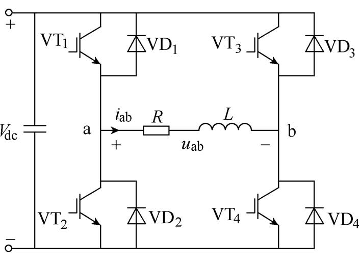
Fig.1 Topology of single-phase voltage inverter
Abstract In random pulse width modulation (RPWM), the instantaneous switching frequency of inverter is required to be distributed in a wide frequency range for better randomness. However, when the switching frequency continues to be high, the switching loss will be increased. When the switching frequency continues to be low, the increase of output current ripples will be introduced. The existing selective harmonic elimination method in RPWM cannot effectively control the switching frequency of inverter as needed in the process of random spread-spectrum. In this paper, a novel hysteresis random spread-spectrum method in RPWM selective harmonic elimination for single-phase inverter is proposed. With the reasonably chosen random number (k) according to the relationship between k and switching frequency in RPWM, the proposed method can guarantee that the instantaneous switching frequency is randomly distributed over a wide range and the average switching frequency can be controlled within a preset range. When the current ripples are large due to low switching frequency in RPWM selective harmonic elimination method, the average switching frequency can be increased to reduce it.
Keywords: Hysteresis random spread-spectrum, random pulse width modulation (RPWM), selective harmonic elimination, single-phase inverter
In the conventional sinusoidal pulse width modulation (SPWM)[1-4], the switching frequency of the inverter is usually fixed and high-order harmonics are generated at the switching frequency and its multiples. This is the main reason for electromagnetic interference (EMI) and electromagnetic noise[5-7]. Increasing the switching frequency can reduce the noise, but it does not work well on occasions where the switching frequency must be limited to low values, such as high-power traction drive systems[8-9]. Random pulse width modulation (RPWM) can distribute the noise power which is concentrated at the switching frequency and its multiples evenly within a certain frequency range[10]. It is an effective method to reduce the electromagnetic noise and EMI at present[11].
RPWM can basically be classified as: random switching frequency PWM[12-13], random pulse position PWM[14], random switching PWM[15], random zero vector PWM[16] and hybrid random PWM[17]. At present, the study focuses of RPWM mainly include: how to generate random numbers and how to calculate the switching period or place the pulse position randomly[18-19]. Thereby, the aforementioned RPWM methods couldn’t eliminate the specific harmonics selectively such as the resonance frequency of the load. The selective harmonic elimination pulse width modulation (SHEPWM)[20] can eliminate specific harmonics, but it is only aimed at low-order harmonics such as 6k±1[21-22] and has little effect on eliminating the high-order harmonics.
In order to shape the noise spectrum of the inverter output voltage, the low-pass filter and the band-pass filter were used respectively to reduce harmonics in the specific frequency range[23-25]. However, the digital filter brings large computation costs. In contrast, a novel idea was suggested in Ref.[26] to calculate the switching period by using the duty ratio to reduce the noise at the specific frequency. This algorithm is simple and the calculation is small. But, with this method, harmonics below 20kHz is usually difficult to eliminate. A method of selective voltage harmonic elimination is proposed in Ref.[27]. The problem in Ref.[26] was better solved and the harmonics whose frequencies are lower than 10kHz can be eliminated. However, the general formulas of the random number k and its corresponding switching frequency extreme value are not given in Ref.[27]. The method of random modulation in Ref.[28] for selectively reducing the noise at one or more frequency points was proposed, but this method led to an increase in the peak of power spectral density (PSD). The noise at the specific frequency can also be reduced in Ref.[29], but the switching frequency of the inverter must be less than the resonance frequency. When the resonance frequency is low, the switching frequency of the inverter will be over low. However, the aforementioned methods can not effectively control the switching frequencies of inverters. Namely, the average switching frequencies of the inverter in Ref.[23-29] can not be increased or decreased according to need.
In RPWM, the instantaneous switching frequency of the inverter is required to be distributed in a wide frequency range[30]. When the switching frequency continues to be high, the switching loss of the IGBT will be increased. Usually, if the switching frequency of the inverter rises to a certain value, the inverter should reduce the rated power by about 5% for every 1kHz increase. When the switching frequency continues to be low, the issues (such as the increase of output current ripples) will be introduced. These all put forward high requirements for inverter switching frequency control. How to control the instantaneous switching frequency and average switching frequency of the inverter optimally are not considered in the aforementioned methods[23-29] when shaping the noise spectrum of the output voltage for the inverter.
This paper proposed a novel hysteresis random spread-spectrum method in RPWM selective harmonic elimination forsingle-phaseinverter. Firstly, the mechanism underlying RPWM selective harmonic elimination is analyzed and two ideas of eliminating specific harmonics in RPWM are derived. Based on the two ideas, the general formulas to calculate the switching period, the random number k and its upper and lower limits ( fkmaxandfkmin) of the switching frequencies are obtained as well. While realizing selective voltage harmonic elimination in RPWM, the average switching frequency can be controlled to increase or decrease according to the need by the frequency hysteresis comparator and reasonably chosen random number k. It is simple and easy to implement.
Topology of single-phase voltage inverter as shown in Fig.1, the bipolar PWM has been adopted in the single-phase voltage inverter. The output voltage (uab) is equal to Vdc or -Vdc.
Fig.1 Topology of single-phase voltage inverter
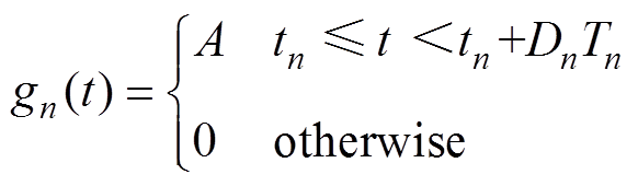
The formulas of the pulse sequence for nth cycle are respectively shown in
 (1)
(1)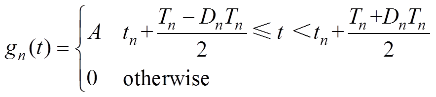 (2)
(2)
In equation (1) and equation (2), A is a constant, Tn is period of nth switching cycle, Dn is duty ratio of nth switching cycle, tn is start time of nth switching cycle and gn(t) indicates the pulse of nth switching cycle.
The PWM pulses are put in the front of the switching period and in the center of the switching period, respectively, as shown in Fig.2a and Fig.2b. A sequence of pulses in Fig.2a and Fig.2b can be regarded as the sum of output voltage (uab) and DC component (Vdc) of Fig.1.
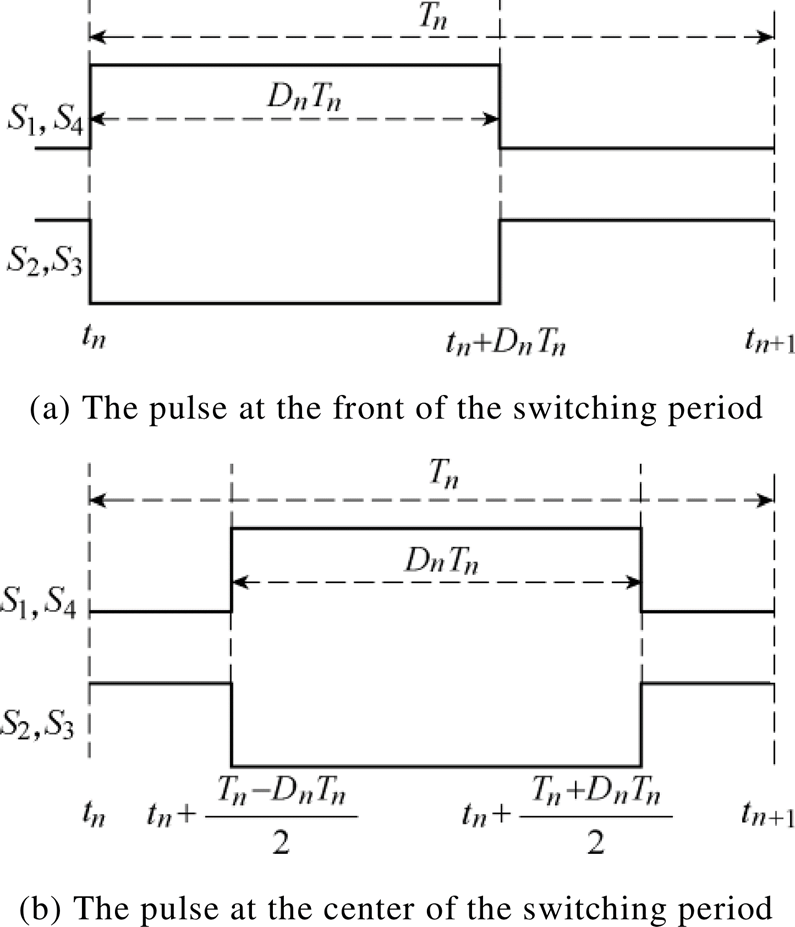
Fig.2 Pulse sequence diagram
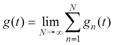
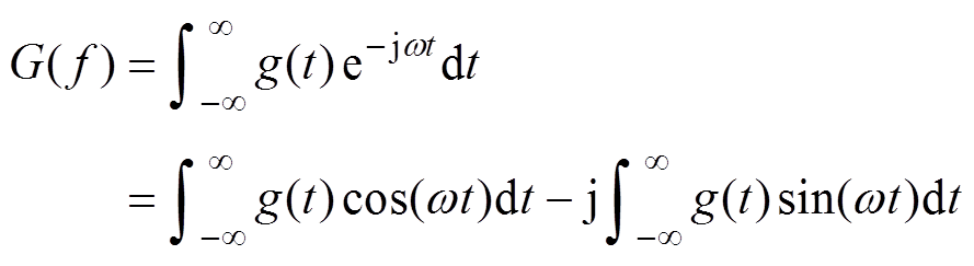
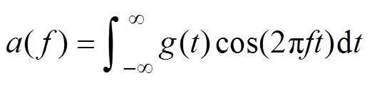
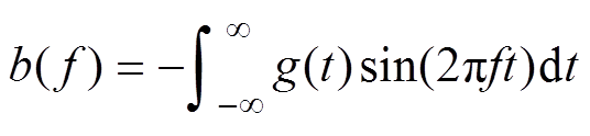
If the pulse function gn(t) does not contain a specific harmonic, then the waveform of uab does notcontain the harmonic. Equation (3) expresses the pulse train. The Fourier transform of equation (3) is given at equation (4). The real and imaginary parts of equation (4) are given at equation (5) and equation (6).
 (3)
(3) (4)
(4)
 (5)
(5)
 (6)
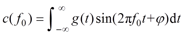
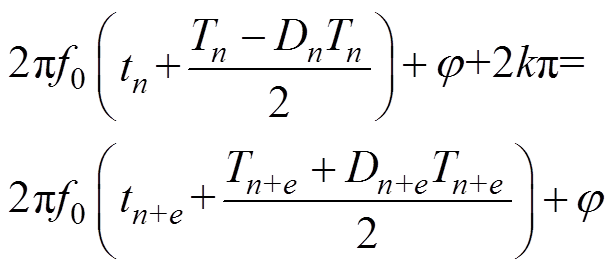
(6)Any is added to the sine function in order to be more universal on the basis of equation (4) to equation (6), as given in equation (7). Equation (8) and equation (9) can be obtained respectively according to the pulse position of Fig.2a and Fig.2b. Assuming that f0 is the harmonic frequency to be eliminated. The purpose of eliminating f0 can be achieved if c( f0) is zero for any
  . In other words, both a( f0) and b( f0) are zero, because a( f0) and b( f0) can be considered as special cases of c( f0).
 (7)
(7)
 (8)
(8) (9)
(9)
In order to make c( f0) be zero for anyand eliminate the specific harmonic frequency f0, two ideas of selective voltage harmonic elimination can be obtained based on equation (7) to equation (9). That is a specific frequency can be eliminated by canceling the front and back terms of different switching cycles.
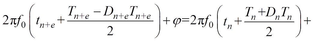
Idea 1 is that the first summation of the (n+e)th term in equation (7) to equation (9) is removed by the second summation of the nth term. The first summation of the (n+e+1)th term is removed by the second summation of the (n+1)th term, etc. Con- sequently, the summations in each term can be removed with each other.
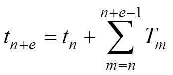
Idea 2 is that the second summation of the (n+e)th term in equation (7) to equation (9) is removed by the first summation of the nth term. The second summation of the (n+e+1)th term is removed by the first summation of the (n+1)th term, etc. Consequently, the summations in each term can be removed with each other. Where tn+e is the start time of (n+e)th switching period and e is a positive integer number.
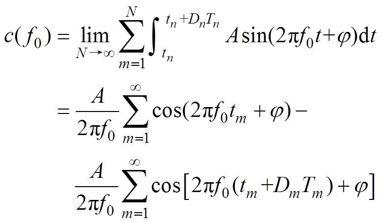
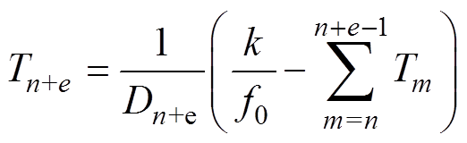
Equation (10) are available according to idea 1 on the basis of equation (8).
 (10)
(10) (11)
(11)
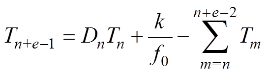
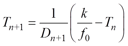
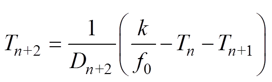
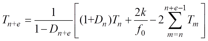
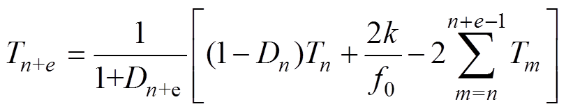
Simultaneously, equation (12) is a general formula of the relation between the switching period and the duty ratio. Equation (13) and equation (14) are obtained when e are equal to 2and 3, respectively. Consequently, the cases canalso be obtained where e are equal to other positive integers. The k in equations are positive random numbers.
 (12)
(12) (13)
(13)
 (14)
(14)
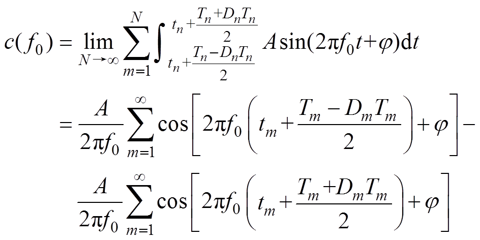
Equation (15) is given according to the idea 2.
 (15)
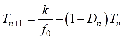
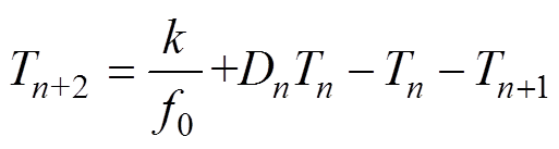
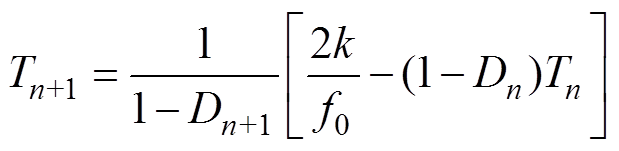
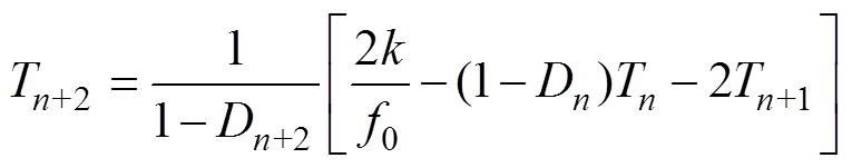
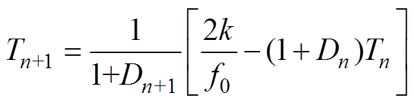
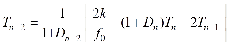
(15)Simultaneously, equation (16) is a general formula of the relation between the switching period and the duty ratio. Equation (17) and equation (18) are obtained when e are equal to 1 and 2, respectively. Consequently, the cases can be obtained where e are equal to other positive integers.
 (16)
(16)
 (17)
(17) (18)
(18)
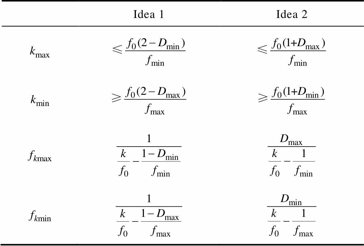
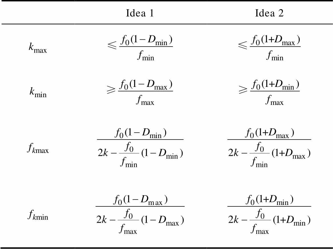
In the idea 1, the general formula (taking Tn+1 as an example) of the upper and lower limits (kmax and kmin) for the random number (k) can be obtained by using equation (13) on the basis of the specific frequency ( f0), the duty ratio and the limit value of switching period, as shown in Tab.1. Similarly, the cases can also be obtained where e are equal to other positive integers.
Tab.1 The  ,
, ,
, and
and  in pulse position at front of switching period
Idea 1Idea 2
In the idea 2, the general formula of the kmax and kmin can be obtained according to equation (17), as shown in Tab.1. Similarly, the cases can also be obtained where e are equal to other positive integers. k is a positive integer in the range of extreme values.
Generally, more than one k in Tab.1 are satisfied. The general formula for each k and its corresponding upper and lower limits of the switching frequencies can be calculated. As shown in Tab.1, the general formulas for each k and its upper and lower limits (fkmax and fkmin) of the switching frequency in the idea 1 and idea 2 can be calculated according to equation (13) and equation (17), respectively. Similarly, the cases can also be obtained where e are equal to other positive integers.
In the Tab.1, Dmaxand Dmin are the upper and lower limits of the duty ratio. fmax and fmin which are usually preseted are the upper and lower limits of the instantaneous switching frequency. k is a positive integer. fkmaxandfkmin are the upper and lower limits of the switching frequency which are derived by each k. Under the same conditions, the larger k is, the smaller the fkmax and fkminare and the smaller k is, the larger fkmax and fkmin are.
It can be seen from the equations of the kmax and kmin in Tab.1 that the range of selection for k is reduced with the decrease of f0. The higher f0 is, the larger the selection range of k is.
Equation (19) are available according to idea 1 on the basis of equation (9).
 (19)
(19)Simultaneously, equation (20) is a general formula of the relation between the switching period and the duty ratio. Equation (21) and equation (22) are obtained when e are equal to 1 and 2, respectively. Consequently, the cases can be obtained where e are equal to other positive integers.
 (20)
(20)
 (21)
(21) (22)
(22)
Equation (23) is available according to the idea 2.
 (23)
(23)Simultaneously, Equation (24) is a general formula of the relation between the switching period and the duty ratio. Equation (25) and equation (26) are obtained when e are equal to 1 and 2, respectively. Consequently, the cases can also be obtained where e are equal to other positive integers.
 (24)
(24)
 (25)
(25) (26)
(26)
As shown in line 2 and line 3 of Tab.2, the extreme values (kmax and kmin) of the random number k can be obtained by using equation (21) and equation (25) according to the idea 1 and idea 2, respectively. k is a positive integer in the range of extreme values. By similar calculation above, the cases where e are equal to other positive integers can be obtained.
Tab.2 The ,, and in pulse position at center of switching period
Idea 1Idea 2
Each k and its upper and lower limits of the switching frequencies in line 4 and line 5 of Tab.2 are calculated according to equation (21) and equation (25). In the same way, the cases where e are equal to other positive integers can also be obtained.
It should be noted that the denominator may have a negative number when using the above equations to calculate fkmax and fkmin. It is shown that the frequency ( f ) and duty ratio (D) can make the denominator of equations be zero without taking the limit value. In this case, the corresponding upper limit frequency is equivalent to +∞.
It can be observed from Tab.1 and Tab.2 that the larger random number (k) is, the smaller fkmax and fkmin are. On the contrary, the limit value of the cor- responding instantaneous switching frequency is larger with a smaller k. This makes it possible to control the average switching frequency of the inverter by reasonably selecting the random number (k). So a smaller k is selected to increase the average switching frequency when the average switching frequency is low. This can prevent the current ripples from increasing caused by the low switching frequency. Similarly, a larger k ischosen to reduce the average switching frequency and switching loss when the average switching frequency is high.
Equation (27) is the formula of the average switching frequency ( fAn) at the start time of the nth sampling cycle according to Fig.2a and the idea 1. In order to avoid repeating the accumulation of the first n-1 switching frequencies in the process of calculating the average, it only needs to multiply the average switching frequency fA(n–1) at the beginning of the previous cycle and the number of cycles, then add it to the previous cycle frequency fn–1 to calculate the average frequency.
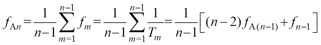 (27)
(27)As shown in Fig.3, the average switching frequency ( fAn) of the inverter was calculated by equation (27) and the upper and lower limits of the frequency hysteresis comparator were set to f1 and f2. The average switching frequency error (Df) is determined according to the result of hysteresis comparison, as shown in equation (28).
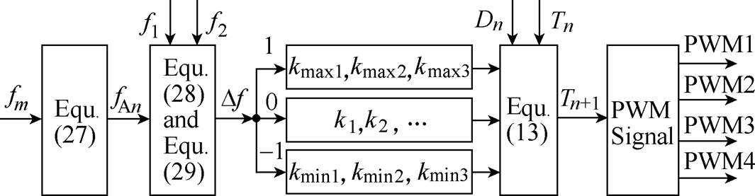
Fig.3 Flow chart of hysteresis random spread-spectrum method in RPWM selective harmonic elimination
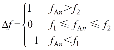 (28)
(28)It means that the average switching frequency is high when is equal to 1. Simultaneously, a k wasselected randomly among the three maximum effective random numbers (kmax1, kmax2, kmax3). Similarly, a k wasselected randomly among the three minimums effective random numbers (kmin1, kmin2, kmin3) when is -1. It means that the average switching frequency is low. Select k from all effective random numbers (k1, k2, k3,…) randomly whenis equal to 0. It means that the average switching frequency is in the effective range. If the number of effective random numbers is less than or equal to 3 at a certain time, the calculation would run according tois 0.
The next sampling cycle (Tn+1) is calculated by using equation (13) after selecting the random number (k) and then the compare registers in DSP is assigned a value. Finally, the PWM driving signal of the single-phase inverter is generated.
The effective k is determined by the upper and lower limits ( fmax and fmin) of the instantaneous switching frequency of the inverter. Among them, the fmax can not exceed the allowable switching frequency of the IGBT and a certain margin is kept. In addition, for those occasions where the carrier frequency must be low, the fmax shall be selected flexibly according to the actual requirements. In this paper,fmax is set to 8kHz and fmin is set to 1.5kHz.
Equation (29) for switching frequency of the inverter is obtained according to the reciprocal of equation (13). The effective random number (k) which satisfies the upper and lower limits of the instantaneous switching can be calculated by equation (29), where fn+1 is the (n+1)th cycle switching frequency of the inverter.
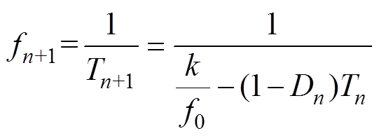 (29)
(29)The upper and lower limits ( f1 and f2) of the average switching frequency hysteresis are con- strained by the upper and lower limits ( fmax and fmin) of the instantaneous switching frequency. In addition, a certain hysteresis width shall be ensured, as shown in equation (30).
 (30)
(30)
In summary, under the premise of ensuring that the instantaneous switching frequency does not exceed the range from fminto fmax, the average frequ- ency is controlled within the set range from f1to f2.
The parameters of the simulation and experi- mental system are as follows: inverter was connected to RL load with R=15W and L=5mH, also the DC voltage is equal to 48V. The instantaneous switching frequency of the inverter is distributed from 1.5kHz to 8kHz. M =0.3, 0.5 and 0.7, also f0=6kHz, 8kHz and 10kHz are preseted, respectively. Duty ratio is achieved from (1+Msin(wt))/2, where wis angular frequency of main harmonic. For instance, the upper and lower limits of duty ratio are equal to 0.85 and 0.15, respectively if M =0.7. The fundamental frequency of the output voltage is 50Hz.
The experimental system is shown in Fig.4. TMS320F2812 32-bit DSP for the master chip of system and the IGBT BSM50GB120DN2 for the main circuit power switches have been adopted. A dead time has been set to 4.27ms. In the experiment, the oscilloscope (DS1052E) and power quality analyzer (HIOKIPW3198) have been used.
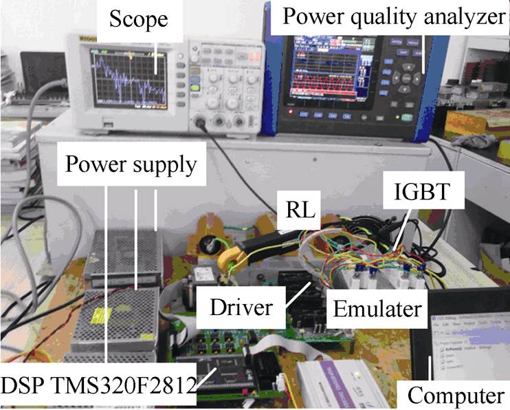
Fig.4 Experimental system
The proposed method is verified by the software of Matlab/Simulink. Fig.5 shows the waveforms of fixed switching frequency 3kHz for SPWM and the conventional RPWM.
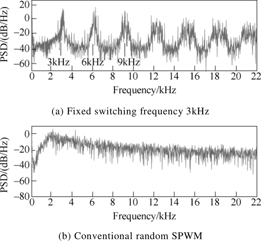
Fig.5 Simulated waveforms of PSD
It can be seen that the harmonics are mainly concentrated at 3kHz and its multiples in Fig.5a. Compared with the fixed switching frequency SPWM, it can be seen from Fig.5b that there is no obvious peak in the PSD of the conventional RPWM and the harmonics are distributed evenly, but it can not selectively eliminate the specific frequency.
The waveforms of the proposed method under the same parameters are shown in Fig.6. Among these figures, the upper and lower limits ( f1 and f2 ) of the average switching frequency are set to 2 100Hz and 4 100Hz, respectively. The f0 is set to 6kHz.
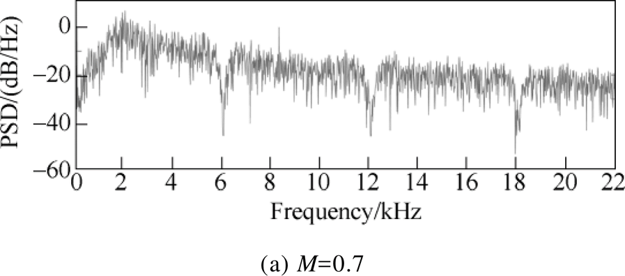
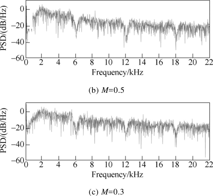
Fig.6 Simulated waveforms of PSD at multiples of 6kHz
Compared with the conventional RPWM, the proposed method can significantly reduce the frequency component of f0 and its multiples, when M are equal to 0.3, 0.5 and 0.7, respectively.
The experimental waveforms of the PSD for the proposed method ( f0=6kHz, 8kHz and 10kHz) are shown in Fig.7. It can be seen that the harmonic power at f0 and its multiples can be reduced significantly when f0 are equal to three frequencies, respectively. It is basically consistent with the simulation results.
As seen in Fig.7, the PSD waveforms have a significant gap with the range of about hundreds hertz around f0 and its multiples. The reason is that the frequency close to f0 is reduced by a certain amplitude when the harmonic power at f0 is completely eliminated. The closer to f0 is, the greater the amplitude is decreased. The impact of phase error in system can be overcome by the characteristics, such as the error in time-delay, etc.
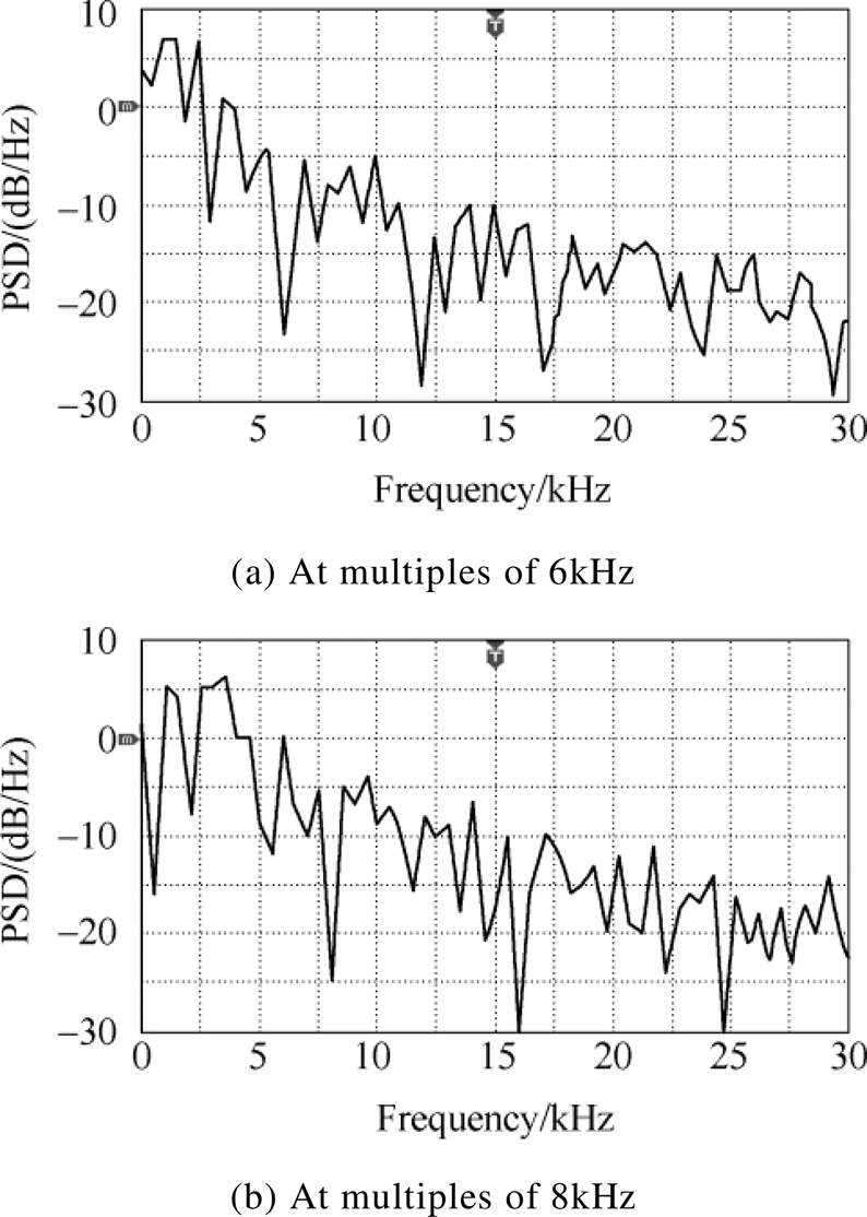
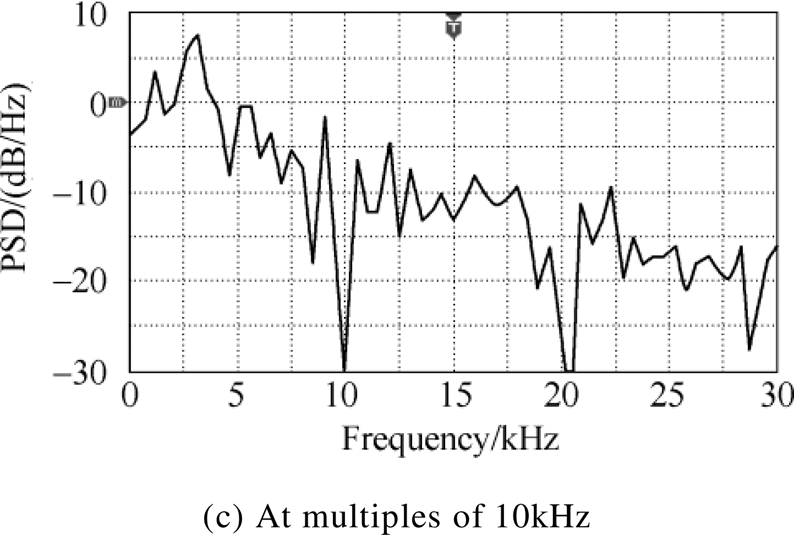
Fig.7 Experimental waveforms of PSD for proposed method when M is 0.7
The experimental waveforms of driving voltage for IGBT, the output voltage and current for the inverter are shown in Fig.8 when f0 is equal to 10kHz.
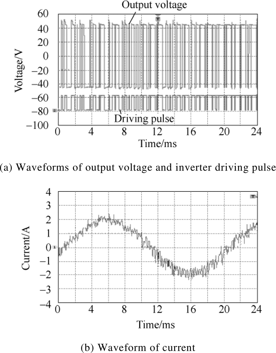
Fig.8 Experimental waveforms of voltage and current
The distribution of instantaneous switching frequency percentage and average switching frequency are shown in Fig.9. Waveforms 1, 2 and 3 are for the proposed method in this paper. The upper and lower limits f1 and f2 of the frequency hysteresis comparator are: 2 100~2 200Hz, 3 000~3 100Hz, 4 000~4 100Hz, also all the hysteresis width is set to 100Hz. Waveform 4 is for the existing RPWM selective harmonic elimination method, taking Ref.[27] as an example. All f0 of aforementioned are 10kHz.
It can be seen from Fig.9 that the average switching frequency can be controlled within the set of three smaller frequency ranges f1~f2 by reasonable selection of the random number. And the instantaneous switching frequency can be ensured to be randomly distributed within the allowable range fmin~fmax. The randomness is well.
In contrast, the existing method in Ref.[23-29] can not control the average switching frequency of the inverter flexibly. The average switching frequency in Ref.[21] is around 3 150Hz in Fig.9a under the same conditions, which is uncontrollable. In this paper, the average switching frequency can be increased to about 4 050Hz and controlled to increase or decrease in the range of 2 100~4 100Hz. So the flexibility is better. The current waveforms for the above two methods are presented in Fig.10 and Fig.11. It can be seen from the comparison that switching frequency of the method in Ref.[27] is lower than the proposed method as a whole and the current ripples are significantly larger.

Fig.9 The waveforms of switching frequency
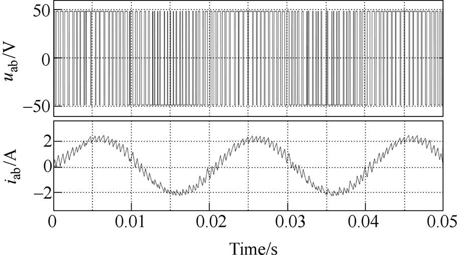
Fig.10 The waveforms of uab and iab when the existing method is adopted
In the method of this paper, the upper and lower limits of the average switching frequency can be obtained if the range of random selection is limited to the maximum three random numbers or the minimum three random numbers. Moreover, the larger f0 is, the more effective random numbers are and the higher the degree and precision of average switching frequency to control is.
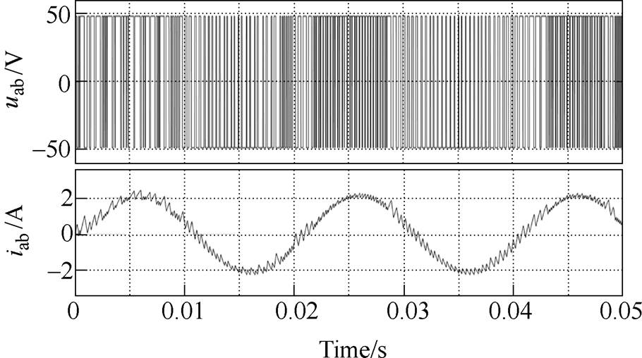
Fig.11 The waveforms of uab and iab when frequency hysteresis is 4 000~4 100Hz
In this paper, a novel hysteresis random spread- spectrum method in RPWM selective harmonic elimination forsingle-phaseinverter has been proposed. Compared with the fixed switching frequency SPWM and the traditional RPWM, the harmonics can be distributed uniformly in certain frequency range and some unwanted harmonics can be eliminated successfully with proposed method. Based on the realization of selective harmonic elimination in RPWM, the flexible increase and decrease of the average switching frequencies have been achieved by the hysteresis random spread-spectrum method. When the current ripple is large due to the low switching frequency, the average switching frequency can be increased to reduce it, while the distribution range of instantaneous switching frequency is unchanged. The proposed method is characterized by flexibility, simple algorithm and easy implementation.
Reference
[1] Chen Jie, Li Jun, Qiu Ruichang, et al. Research on space vector PWM synchronous overmodulation in rail transit traction system[J]. Transactions of China Electrotechnical Society, 2020, 35(S1): 91-100.
[2] Niu Feng, Cao Shiran, Wang Yao, et al. Analysis of leakage current in PWM motor system[J]. Transa- ctions of China Electrotechnical Society, 2019, 34(8): 1599-1606.
[3] Liu Jianqiang, Liu Chuanduo, Wang Yiou, et al. Fault diagnosis method for IGBT and DC-link capacitor of single-phase PWM rectifier[J]. Transactions of China Electrotechnical Society, 2019, 34(S1): 244-257.
[4] Xia Wenjing, Liu Bi, Wang Song, et al. Model predictive control of PWM rectifiers based on dyna- mic component optimization of input-port voltage[J]. Automation of Electric Power Systems, 2020, 44(1): 200-207.
[5] Hara T, Ajima T, Tanabe Y, et al. Analysis of vibration and noise in permanent magnet synchronous motors with distributed winding for the PWM method[J]. IEEE Transactions on Industry Appli- cations, 2018, 54(6): 6042-6049.
[6] Jiang Shiqi, Liu Yitao, Yin Shan, et al. Electro- magnetic interference filter design of single-phase inverter based on the noise source impedance extraction[J]. Transactions of China Electrotechnical Society, 2019, 34(17): 3552-3562.
[7] Li Jie, Xu Yuan, Song Wenxiang. CHMPWM for active-neutral-point-clamped five-level converter and flying capacitor voltage control[J]. Electric Machines and Control, 2019, 23(9): 92-100.
[8] Wang Chenchen, Wang Kun, You Xiaojie, et al. Research on the synchronized SVPWM strategies under low switching frequency for dual stator indu- ction machines[J]. Proceedings of the CSEE, 2017, 37(13): 3883-3891.
[9] Chen Minwu, Liu Ruofei, Chen Ling, et al. Com- pensation algorithm and control strategy optimization of combined co-phase power supply system[J]. Electric Machines and Control, 2019, 23(8): 28-34, 42.
[10] Liu Zhen, Wei Yingdong, Jiang Qirong. Random zero-sequence component modulation of MMC based on IGBT series modular[J]. Automation of Electric Power Systems, 2017, 41(11): 156-162.
[11] Lezynski P. Random modulation in inverters with respect to electromagnetic compatibility and power quality[J]. IEEE Journal of Emerging and Selected Topics in Power Electronics, 2018, 6(2): 782-790.
[12] Bhattacharya S, Mascarella D, Joos G, et al. Reduced switching random PWM technique for two-level inverters[C]//2015 IEEE Energy Conversion Congress and Exposition (ECCE), Montreal, QC, CAN, 2015: 695-702.
[13] Bu Feifei, Pu Tianyu, Huang Wenxin, et al. Perfor- mance and evaluation of five-phase dual random SVPWM strategy with optimized probability density function[J]. IEEE Transactions on Industrial Electro- nics, 2019, 66(5): 3323-3332.
[14] Paramasivan M, Paulraj M M, Balasubramanian S. Assorted carrier-variable frequency-random PWM scheme for voltage source inverter[J]. IET Power Electronics, 2017, 10(14): 1993-2001.
[15] Agelidis V G, Vincenti D. Optimum non-deterministic pulse-width modulation for three-phase inverters[C]// Proceedings of IECON '93-19th Annual Conference of IEEE Industrial Electronics, Maui, HI, USA, 1993: 1234-1239.
[16] Liu Yang, Wang Qingyi, Zhao Jin. Dual randomized PWM based on vector control system[J]. Proceedings of the CSEE, 2010, 30(36): 98-102.
[17] Huang Yingliang, Xu Yongxiang, Zhang Wentao, et al. Hybrid RPWM technique based on modified SVPWM to reduce the PWM acoustic noise[J]. IEEE Transactions on Power Electronics, 2019, 34(6): 5667-5674.
[18] Gamoudi R, Elhak Chariag D, Sbita L. A review of spread-spectrum-based PWM techniques-a novel fast digital implementation[J]. IEEE Transactions on Power Electronics, 2018, 33(12): 10292-10307.
[19] Jadeja R, Ved A, Chauhan S. An investigation on the performance of random PWM controlled converters[J]. Engineering, Technology & Applied Science Research, 2015, 5(6): 876-884.
[20] Sharifzadeh M, Vahedi H, Portillo R, et al. Selective harmonic mitigation based self-elimination of triplen harmonics for single-phase five-level inverters[J]. IEEE Transactions on Power Electronics, 2019, 34(1): 86-96.
[21] Yang Kehu, Yuan Zhibao, Yuan Ruyi, et al. A groebner bases theory-based method for selective harmonic elimination[J]. IEEE Transactions on Power Electro- nics, 2015, 30(12): 6581-6592.
[22] Pérez-Basante A, Ceballos S, Konstantinou G, et al. A universal formulation for multilevel selective- harmonic- eliminated PWM with half-wave symmetry[J]. IEEE Transactions on Power Electronics, 2019, 34(1): 943- 957.
[23] Kang B J, Liaw C M. Random hysteresis PWM inverter with robust spectrum shaping[J]. IEEE Transactions on Aerospace and Electronic Systems, 2001, 37(2): 619-629.
[24] Liu Heping, Liu Qing, Zhang Wei, et al. Random PWM technique for acoustic noise and vibration reduction in induction motors used by electric vehicles[J]. Transactions of China Electrotechnical Society, 2019, 34(7): 1488-1495.
[25] Chai J Y, Lin Y W, Liaw C M. Comparative study of switching controls in vibration and acoustic noise reductions for switched reluctance motor[J]. IEE Pro- ceedings-Electric Power Applications, 2006, 153(3): 348-360.
[26] Kirlin R L, Lascu C, Trzynadlowski A M. Shaping the noise spectrum in power electronic inverters[J]. IEEE Transactions on Industrial Electronics, 2011, 58(7): 2780-2788.
[27] Peyghambari A, Dastfan A, Ahmadyfard A. Strategy for switching period selection in random pulse width modulation to shape the noise spectrum[J]. IET Power Electronics, 2015, 8(4): 517-523.
[28] Pedersen J K, Blaabjerg F, Frederiksen P S. Reduction of acoustic noise emission in AC-machines by intelligent distributed random modulation[C]//Fifth European Conference on Power Electronics and Applications, Brighton, UK, 1993, 4: 369-375.
[29] Wang Zheng, Chau K, Cheng Ming. A chaotic PWM motor drive for electric propulsion[C]//IEEE Vehicle Power and Propulsion Conference, Harbin, China, 2008: 1-6.
[30] Lee K, Shen G, Yao W, et al. Performance characteri- zation of random pulse width modulation algorithms in industrial and commercial adjustable-speed drives[J]. IEEE Transactions on Industry Applications, 2017, 53(2): 1078-1087.
摘要 在随机脉冲宽度调制(RPWM)中,要求逆变器的瞬时开关频率分布在较宽的频率范围内,以获得较好的随机性。然而,当开关频率持续偏高时,逆变器的开关损耗将会增加;当开关频率持续较低时,会引起输出电流纹波的增加。现有的RPWM选择性谐波消除方法在随机扩频的过程中不能有效地控制逆变器的开关频率。该文提出一种单相逆变器RPWM选择性消谐滞环随机扩频方法。根据RPWM策略中有效随机数k与开关频率的关系,合理选择随机数k,既可以保证逆变器瞬时开关频率在较宽的范围内随机分布,又可以将平均开关频率控制在预先设定的频率范围内。在RPWM选择性消谐过程中,当开关频率较低而引起电流纹波增加时,该方法可以通过提高平均开关频率来减小纹波。
关键词:滞环随机扩频 随机脉宽调制(RPWM) 选择性谐波消除 单相逆变器
中图分类号: TM46
DOI: 10.19595/j.cnki.1000-6753.tces.200018
This work is partially supported by National Natural Science Foundation of China (51307076) and Natural Science Foundation of Liaoning Province, China (20180550268).
Received January 7, 2020;
Revised March 3, 2020.
Notes Brief
Li Guohua male, born in 1981, PhD. Major research interests include power electronics, pulse-width modulation schemes and harmonic compensation in power system.E-mail: dkliguohua@163.com
Liu Chunwu male, born in 1995, Postgraduate. Major research interests include power electronics and pulse-width modulation schemes.E-mail: lcw19950204@163.com (Corresponding author)
(编辑 陈 诚)