Fig.1 The structure of the 120°-TPMLG
Abstract The utilization of 120° phase belt toroidal windings can bring power density improvement in a tubular permanent magnet linear generator (TPMLG). However, the TPMLG always suffers from large detent force, which would cause generator oscillation or even destabilize the system. To alleviate this problem, the optimal design of the tubular permanent magnet linear generator with 120° phase belt toroidal windings (120°-TPMLG) is conducted in this paper. The influence of different structural parameters (stator iron core length, pole arc coefficient, slot shoulder width, stator teeth width and air gap length) on the detent force is analyzed via finite element method firstly. According to these analytical results, the optimal design combined with the Taguchi method is implemented to minimize the detent force without losing output power, and the optimal structural parameters of the 120°-TPMLG are obtained. To verify the effectiveness of the optimal design process, the performance of the optimal 120°-TPMLG is compared with that of the original one. It is shown that the detent force of the optimal generator is largely decreased, and the output power is slightly improved, which proves that the proposed optimal design method is available in the detent force reduction of 120°-TPMLG.
Keywords: 120° phase belt toroidal windings, detent force, optimal design, tubular permanent magnet linear generator, Taguchi method
Nowadays, linear generators have been a promising choice for the direct-drive wave energy conversion (DD-WEC) systemowing to simple structure, friendly maintenance and high efficiency[1]. Unfortunately, common linear generators used in DD-WEC system have the drawback of low power density due to their low operation speed. Accordingly, many special types of generators have been applied in DD-WEC system for power density improvement, such as double-fed linear generator, variable reluctance linear generator, and permanent magnet linear generator (PMLG)[2-3]. The PMLG rises the most attention among these generators because ofthe advantages of high force-to-weight ratio, and high efficiency as well as high power factor[4]. The PMLG for DD-WEC system generally has tubular structure, which inherits the merits of high winding utilization rate and power density[5].
Common tubular PMLGs usually adoptfractional pitch windings, which maycause a space vectors misalignment of coil-EMF, and a little dip of the no-load EMF. It will limit the output power improvement.To further improve the power density, a tubular PMLG with 120° phase belt toroidal windings(120°-TPMLG) is proposed. Its analysis results show that the 120°-TPMLG has the advantage that high power density and high efficiency[6-7]. However, the detent force of the 120°-TPMLG is slightly higher than that of the traditional TPMLG due to its special slot/pole ratio[8].The detent force can cause undesirable mechanical vibration, which makes the generation difficult to work, especially under the condition of low wave speed[9]. Therefore, it is of great significance to reduce the detent force for the 120°-TPMLG.
In recent years, many detent force reduction methods from motor design technologieshave been proposed and investigated, such as skewing, stator core optimization, magnet shift and semi-closed stator slots, etc[10-14]. However, most of the aforementioned methods mainly focus on the optimization of single objective, by which it is difficult to obtain the optimal parameters for two or more objectives. Accordingly, numerous multi-objective optimization methods have been proposed, such as genetic algorithm, surface response method and Taguchi method[15-17], etc. Appling the genetic algorithm in the optimization of the tubular PMLG has a major shortcoming thatit is very time-consuming especially for the high- dimensional characteristic of the optimization[18]. Additionally, the optimization accuracy is not acceptable due to the essential assumptions and objective functions. The response surface (RS) method can be also utilized in optimizing the structure parameters of the TPMLG. Although it can reduce the computation time, it is hard to cover all sample points and goodness of fit due to the nonlinearity of the optimization[19]. By contrast, the Taguchi method can allow many settings of necessary structure parameters in design optimization simultaneously without complicated algorithms and additional programming. Hence, effects of several factors on motor perfor- mance can be investigated simultaneously with a little time[20-21]. Accordingly, the Taguchi method is utilized to minimize the detent force without losing power density in this paper.
This paper adopts the Taguchi method to conduct the optimal design of the 120°-TPMLG for the detent force reduction. Through theoretical and finite element analysis (FEA), five key structural parameters are selected to be as the design variables to obtain the best combination of structure parameters. The optimal generator model of the 120°-TPMLG is constructed, and its performances are analyzed and compared with those of the initial one and the traditional TPMLG. The comparison results can prove the effectiveness of the Taguchi method in the detent force reduction.
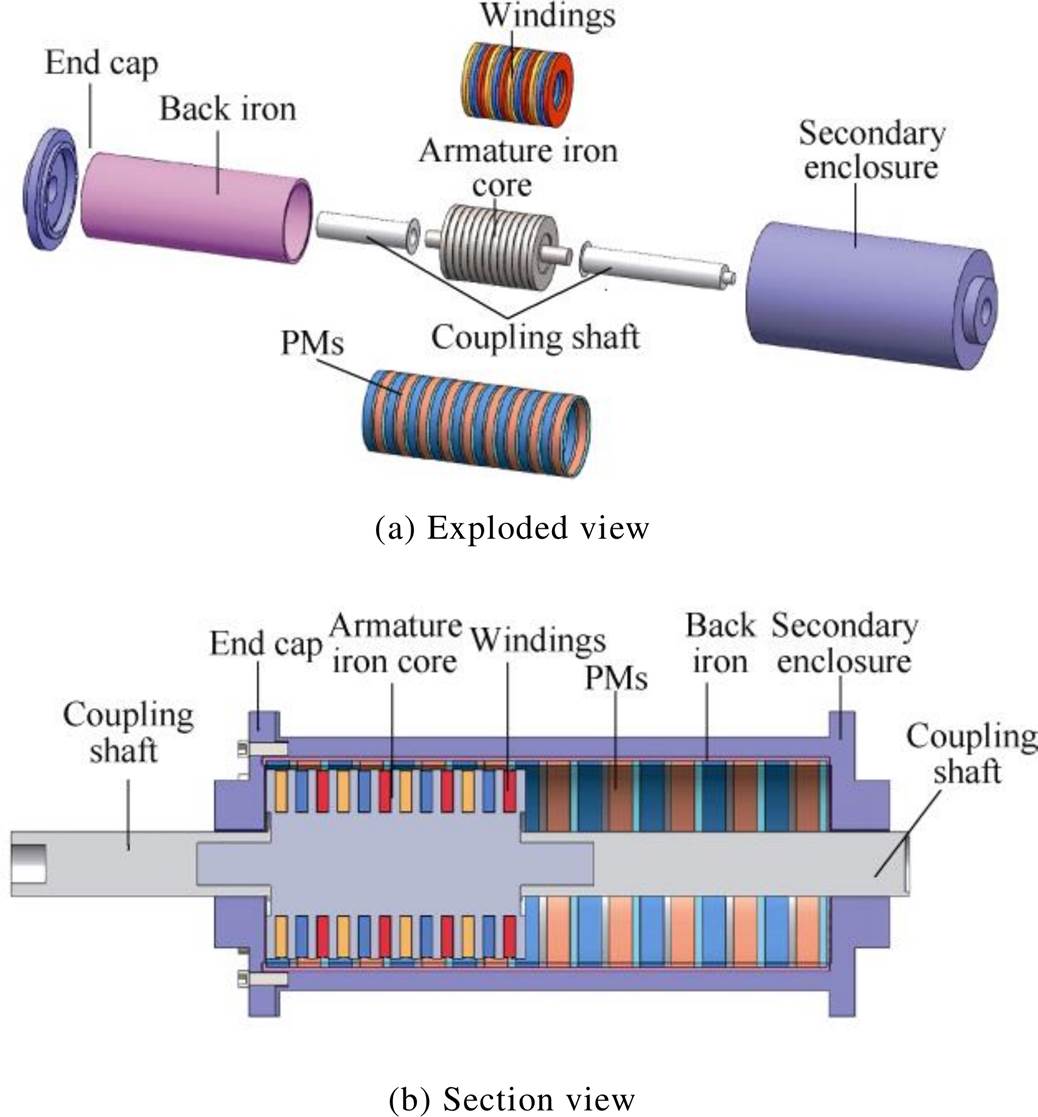
The 120°-TPMLG is proposed to improve the power density for DD-WEC system. Its structure of the 120°-TPMLG is depicted in Fig.1.
Fig.1 The structure of the 120°-TPMLG
As shown in Fig.1, the structure of the 120°- TPMLGconsists of a primary part (stator) and a secondary part (mover). The primary part, which includes an armature iron core and120° phase belt toroidal windings, is fixed. The secondary part, which is made up of permanent magnets with quasi-Halbach magnetizationand back iron, is connected to the buoy. As the secondary part moves vertically along with the buoy, the magnetic flux generated by the permanent magnets passes the 120° phase belt toroidal windings, and the induction electromotive force is obtained.
The Fig.1 shows that the stator of 120°-TPMLG is provided with 12 annular slots along the axial direction. And each slot is embedded with a self-contained toroidal winding, which increases the heat dissipation area and improves the thermal performance. Additionally, the 120°-TPMLG is good in insulation due to the windings independent of each other. The windings configuration of the 120°- TPMLG and thetraditional TPMLG are depicted in Fig.2. The symbols A, B and C represent the incoming line ends of the windings, and the symbols X, Y and Z represent the outgoing line ends of the windings.
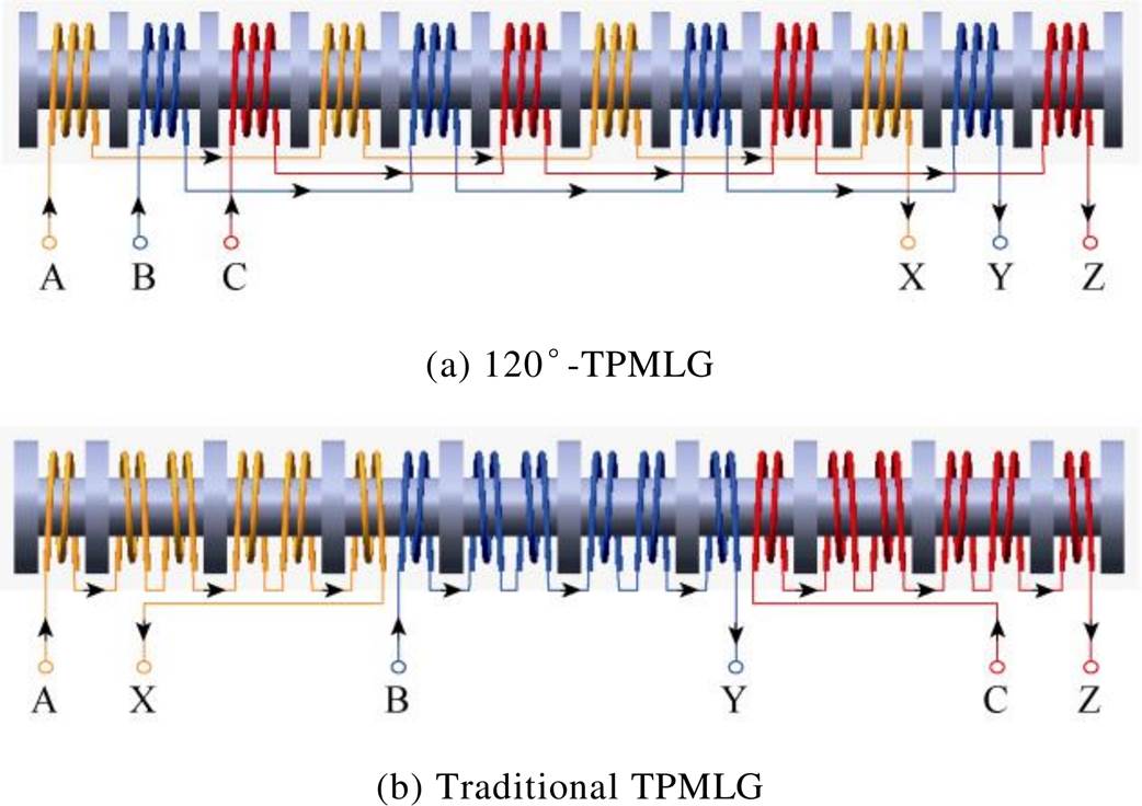
Fig.2 Windings configuration of the two generators
The differences between the 120°-TPMLG and the traditional TPMLG are the slot/pole ratio and the windings configuration. The 120°-TPMLG adopts an 8-pole/12-slot structure, and the incoming ends of the windings is not only located in the same side of the stator core, but also have the same orientation. While the traditional TPMLG has a 9-pole/10-slot structure, and the incoming ends of the windings distribute on both sides of the stator core and have different orientations.
The main parameters of the 120°-TPMLG and the traditional TPMLG are determined by the analytical method[22] and shown in Tab.1.
Based on Tab.1, the initial design model of the 120°-TPMLG and traditional TPMLG are established and their detent force are compared and shown in Fig.3.
Tab.1 Main parameters of the 120°-TPMLG and traditional TPMLG
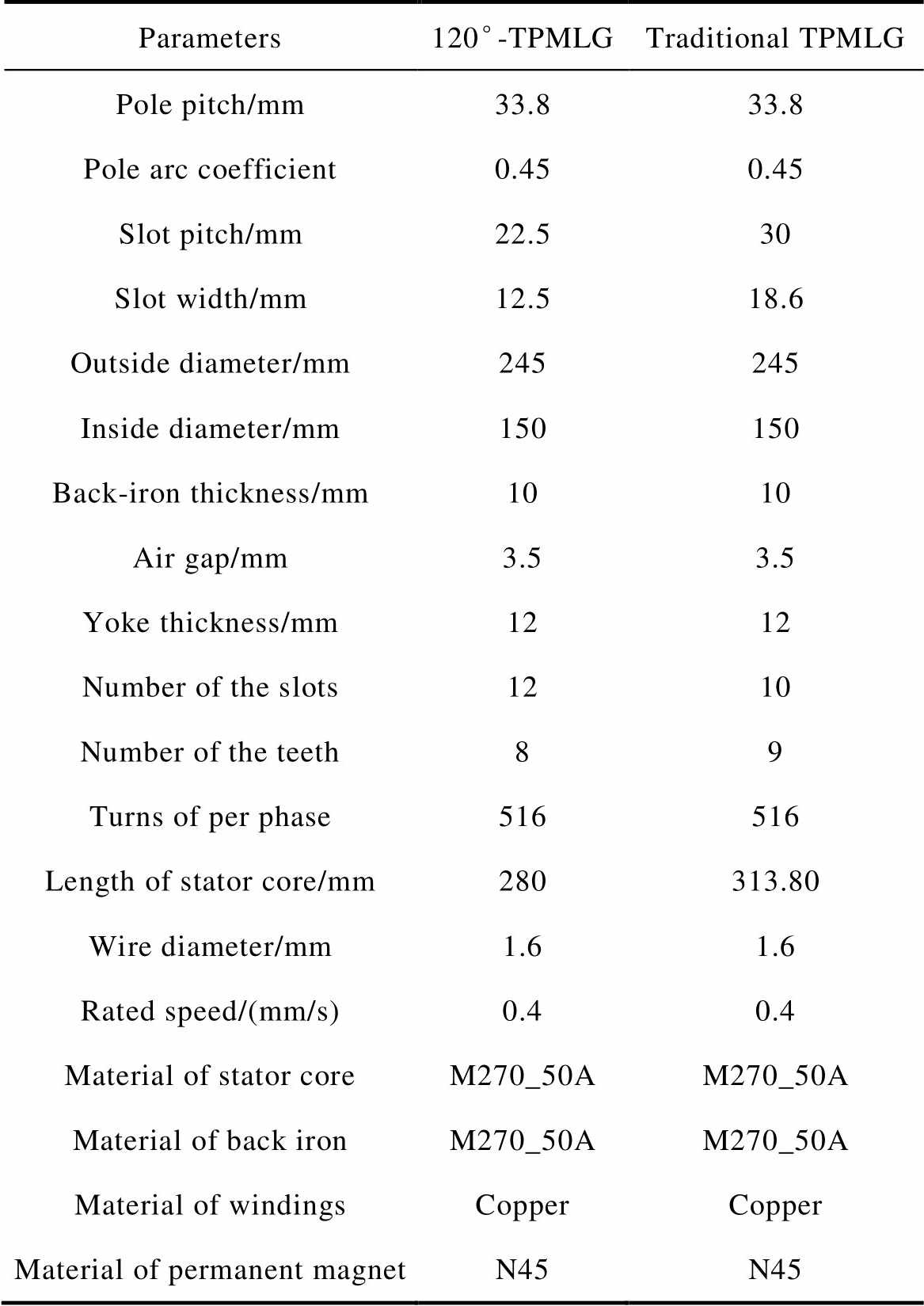
Parameters120°-TPMLGTraditional TPMLG Pole pitch/mm33.833.8 Pole arc coefficient0.450.45 Slot pitch/mm22.530 Slot width/mm12.518.6 Outside diameter/mm245245 Inside diameter/mm150150 Back-iron thickness/mm1010 Air gap/mm3.53.5 Yoke thickness/mm1212 Number of the slots1210 Number of the teeth89 Turns of per phase516516 Length of stator core/mm280313.80 Wire diameter/mm1.61.6 Rated speed/(mm/s)0.40.4 Material of stator coreM270_50AM270_50A Material of back ironM270_50AM270_50A Material of windingsCopperCopper Material of permanent magnetN45N45
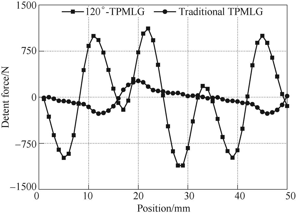
Fig.3 Comparison of the detent force of the 120°-TPMLG and traditional TPMLG
As shown in Fig.3, the maximum detent force of the 120°-TPML is 1 150N, which is about 4.06 times that of the traditional TPMLG. The detent force would seriously affect the performance of the generator. Therefore, it is necessary to reduce the detent force of the 120°-TPMLG.
The components of the detent force of the 120°- TPMLG are analyzed and shown in Fig.4.
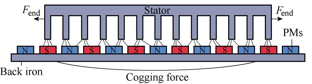
Fig.4 Components of the detent force in the 120°-TPMLG
It can be seen from the Fig.4, the detent force existing in the 120°-TPMLG consists of two elements: one is the end effect force due to the finite length of stator, and the other is the cogging force for the mutual attractive between permanent magnets and the stator teeth.
For the arbitrarily length of the stator iron coreLs=ktp-d, the end effect force[23] can be expressed as
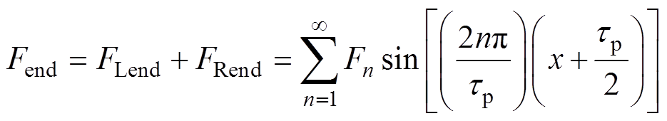 (1)
(1)where
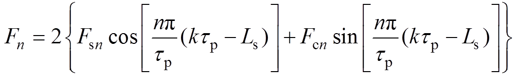 (2)
(2)
where FLend and FRend are the left and the right end effect force respectively, Fsn and Fcn are the magnitude of the nth harmonic component,tp is the pole pitch of the generator.
According to the formula (1) and formula (2), as one can see that the end effect force is proportional to Fn, and the Fn has close relationship with Ls. Therefore, the Ls can largely affect the end effect force. End effect force under different length of the stator iron core are obtained by magnet software, and they are shown in Fig.5.
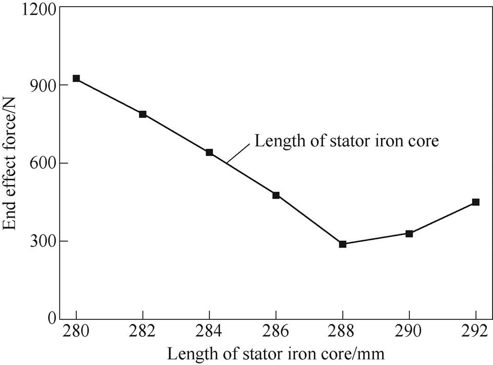
Fig.5 End effect force of the 120°-TPMLG under different length of stator iron core
As shown in Fig.5, the different length of the stator iron core (L) corresponds to the different values of end effect force. While L=280mm, the maximum end effect force is 925N. After optimization, it drops to 288N at L=288mm, which means that 68.86% of end effect force can be reduced by changing the length of stator iron core.
The cogging force[24] can be expressed as
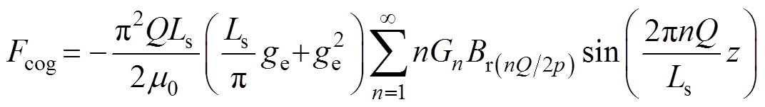 (3)
(3)where

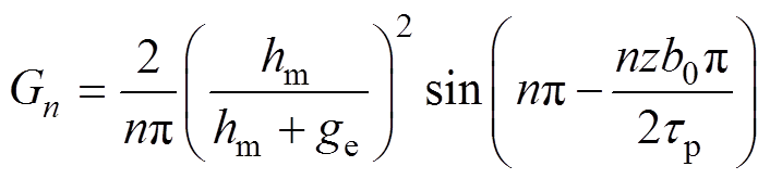 (4)
(4)
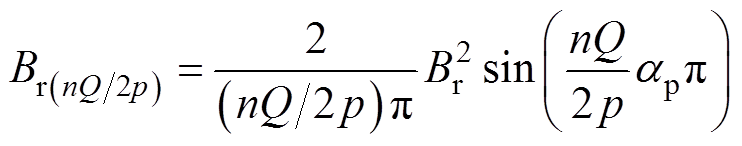 (5)
(5)where Ls is length of the stator iron core, ge is the effect air gap, Gn is the magnitude of nth harmonic component, Br(nQ/2p) is (nQ/2p)th harmonic component of remanence, Q is the number of slots, b0 is the width of slot, ap is the pole arc coefficient.
According to the formula (3) and formula (4), as one can see that the cogging force is proportional to the Gn. And the Gn has close relationship with the b0. Therefore, the b0 can largely affect the cogging force. The b0 can be adjusted by changing the width of stator tooth. The cogging force for different width of the stator tooth are shown in Fig.6.
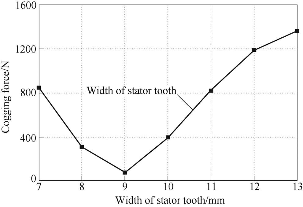
Fig.6 Cogging force of the120°-TPMLG under different width of stator tooth
As shown in Fig.6, the different width of the stator tooth (T) corresponds to the different values of cogging force. While T=13mm, the maximum cogging force is 1 360N, but while T=9mm, it is only 79N, which means that the cogging force can be largely reduced by choosing a suitable width of the stator tooth.
Additionally, the b0 can be adjusted by adopting the slot shoulders. The cogging force under different width of slot shoulders are obtained by magnet software and shown in Fig.7.
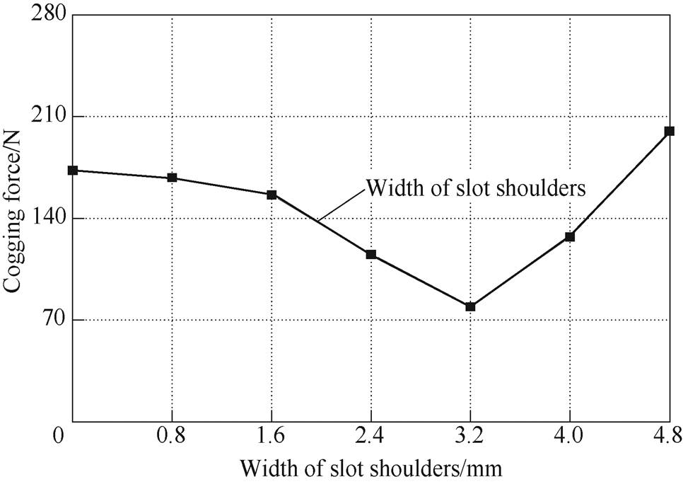
Fig.7 Cogging force of the 120°-TPMLG under different width of slot shoulders
As shown in Fig.7, the cogging force for the width of slot shouldersW=3.20mm is 79N, which is decrease about 60.50% from the 200N for W=4.80mm, which means that the cogging force can be decrease effectively by adopting a suitable width of the slot shoulders.
According to the formula (3) and formula (5), as one can see that the cogging force is proportional to the Br(nQ/2p) and the Br(nQ/2p) has close relationship with the ap. Therefore, the pole arc coefficient can largely affect the cogging force. Cogging force for different pole arc coefficient is shown in Fig.8.
As shown in Fig.8, when the width of air-gap increases to 0.78mm from 0.48mm, the maximum cogging force decreases to 79N from 538N.And the value of the cogging force has an upward trend with the increase of pole arc coefficient, which means that the cogging force has been closely related with the pole arc coefficient.
The end effect force works together with the cogging force, resulting in a large detent force. And the expression of the detent force[25] can be written
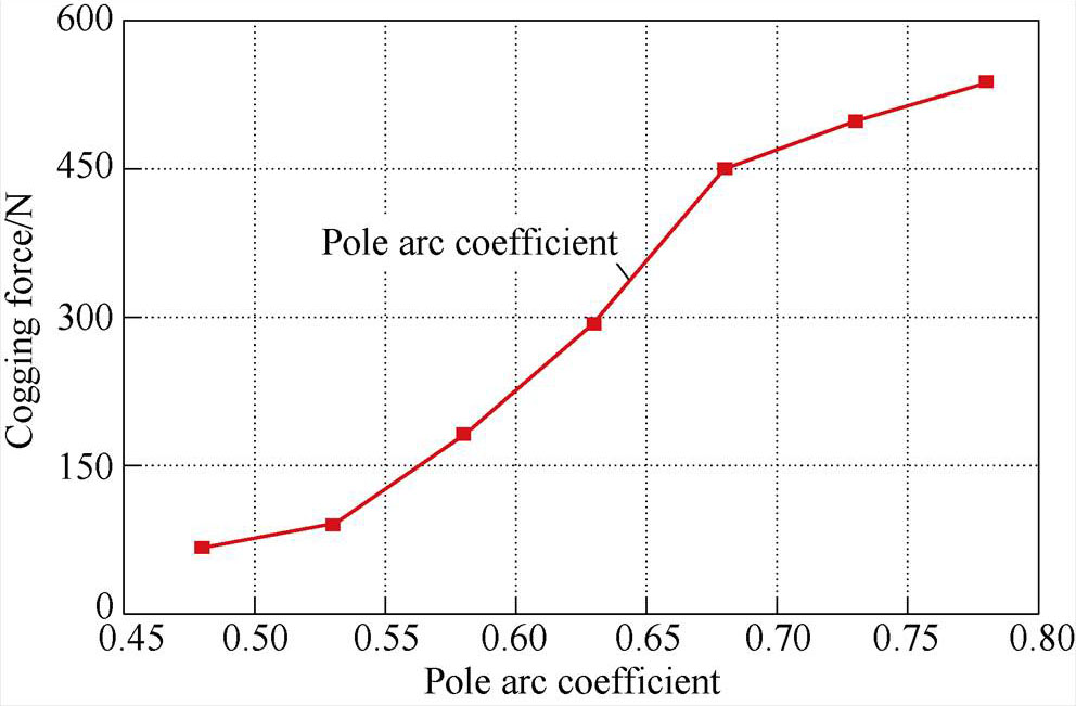
Fig.8 Cogging force of the 120°-TPMLG under different pole arc coefficient
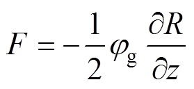 (6)
(6)where
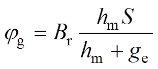 (7)
(7)
where jg is the air-gap flux, R is the air-gap reluctance, ∂R/∂z is the rate of the air-gap reluctance, hm is the magnetization length of the permanent magnet, S is the magnetization area of the permanent magnet.
From the formula (6) and formula (7), as one can see that the detent force is proportional to jg, and the jg is inverse toge. Therefore, an assumption is withdrawn that the detent force is inverse toge. The detent force for different width of air gap is shown in Fig.9.
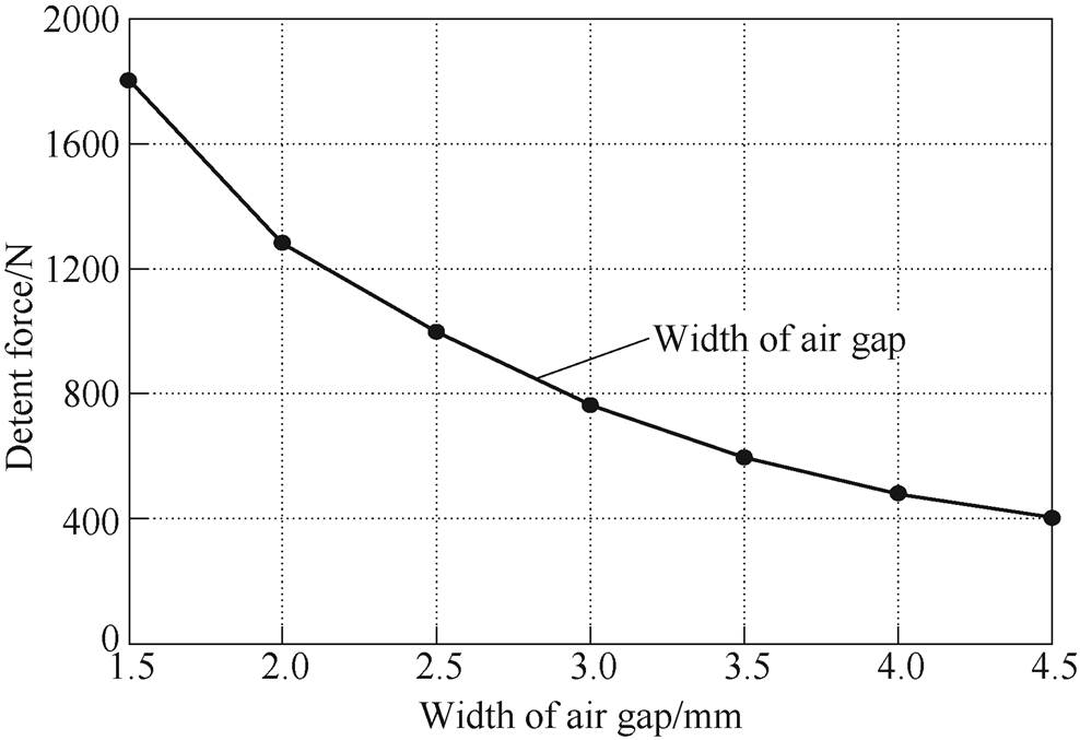
Fig.9 Detent force of the 120°-TPMLG under different width of air gap
As shown in Fig.9, When the width of air-gap increases to 4.50mm from 1.50mm, the maximum detent force decreases to 402N from 1 803N.The value of the detent force has a downward trend with the increase of width of air-gap, which verify the correctness of the aforementioned assumption.
In this paper, the Taguchi method is applied in the structure parameters optimization of the 120°- TPMLG for the reduction of the detent force. And there are five steps for multi-objective optimal design using Taguchi design method:
(1) Identify design variables and objective functions.
(2) Identify levels of design variables.
(3) Define orthogonal array for Taguchi design.
(4) Design the matrix experiment and conduct the matrix experiment by FEM.
(5) Multi-objective optimal design with weighting set of each objective functions.
The objective of the structure optimization of the 120°-TPMLG is to minimize the detent force without losing output power. Accordingly, the detent force (F) and output power (Pout) are selected to be optimized as the objective functions. There are many design variables related to detent force and output power. For the optimal design, it is necessary to reduce design variables to get feasible optimal design result in a short time. Therefore, five representative factors are chosen as design variables in this paper, which is stator iron core length, pole arc coefficient, slot shoulders width, stator tooth width and air gap length, respectively.
The design variables and their respective levels are given in Tab.2, where A is the stator iron core length, B is the pole arc coefficient, C is the stator tooth width,D is the slot shoulders width and E is the air gap length.
Tab.2 The respective levels of the design variable

VariableA/mmBC/mmD/mmE/mm Level 12840.4871.62 Level 22860.5382.42.5 Level 32880.5893.23 Level 42900.631043.5 Level 52920.68114.84
According to the number of the design variables and their settings, a standard orthogonal array L25 is selected for the matrix numerical experiment. And matrix experiment results are obtained by magnet software and shown in Tab.3.
Tab.3 Experimental results of objective function
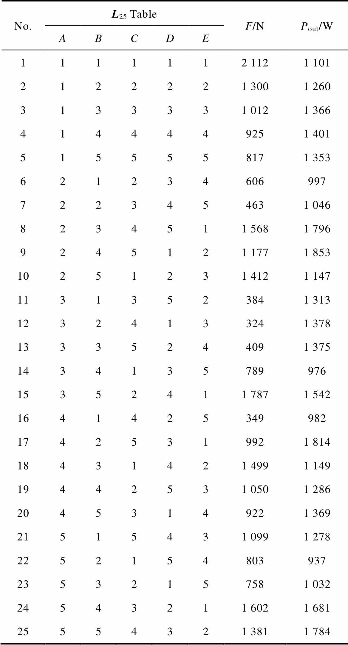
No.L25TableF/NPout/W ABCDE 1111112 1121 101 2122221 3001 260 3133331 0121 366 4144449251 401 5155558171 353 621234606997 7223454631 046 8234511 5681 796 9245121 1771 853 10251231 4121 147 11313523841 313 12324133241 378 13335244091 375 1434135789976 15352411 7871 542 1641425349982 17425319921 814 18431421 4991 149 19442531 0501 286 20453149221 369 21515431 0991 278 2252154803937 23532157581 032 24543211 6021 681 25554321 3811 784
After conducting these 25 numerical experiments and obtaining all the experimental data, “Analysis of Means” (ANOM) and “Analysis of Variance” (ANOVA) are carried out for estimating the effects of the five design variables and for determining the relative importance of each design variables. The optimum settings for each design variables are then obtained from the plot of main factor effects.
3.4.1 Analysis of means (ANOM)
The means of all experiments results can be calculated as
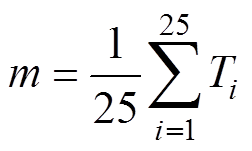 (8)
(8)Tab.4 tabulates the results.
Tab.4 Analysis of means
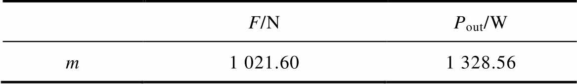
F/NPout/W m1 021.601 328.56
3.4.2 Calculate average effect
The value of average detent force of setting variable A at level 1 is calculated by
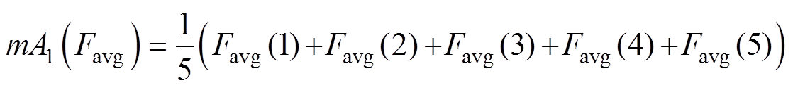 (9)
(9)where the variable A is set to level 1 only in experiments 1 to 5 as shown in Tab.3. Average value of detent force of all variables can be obtained by a similar way. Tab.5 shows the results. A plot of the main factors effects is shown in Fig.10. It is seen that the factor-level combination (A3, B2, C3, D5, E5) contributes to minimum value of detent force.
Tab.5 Maximum detent force for all levels of factors
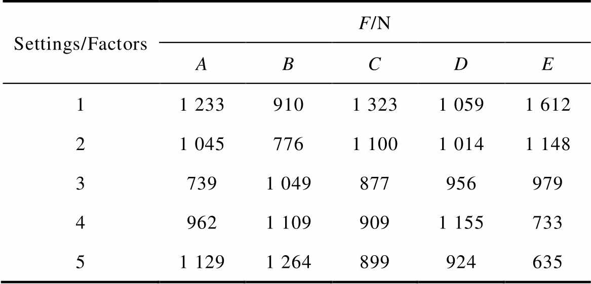
Settings/FactorsF/N ABCDE 11 2339101 3231 0591 612 21 0457761 1001 0141 148 37391 049877956979 49621 1099091 155733 51 1291 264899924635
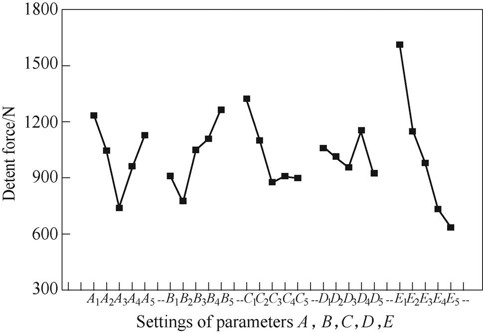
Fig.10 Plot of main factor effects on the detent force
In a similar way, the average value of output power can be obtained for all levels of factors. The results are shown in Tab.6. Fig.11 illustrates the main factor effect on the value of output power. It is seen that factor-level combination (A2, B4, C5, D3, E1) contributes to maximization of output power.
Tab.6 Output power for all levels of factors
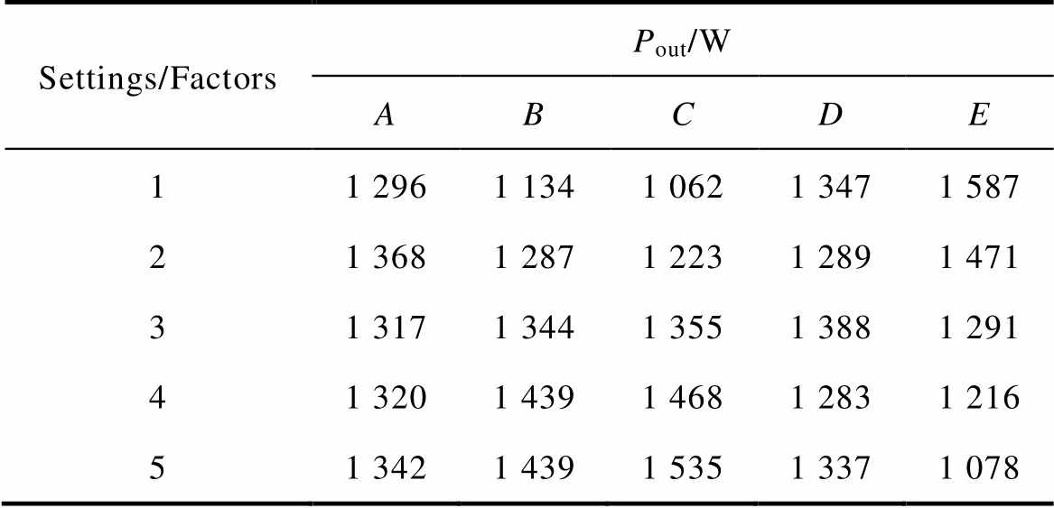
Settings/FactorsPout/W ABCDE 11 2961 1341 0621 3471 587 21 3681 2871 2231 2891 471 31 3171 3441 3551 3881 291 41 3201 4391 4681 2831 216 51 3421 4391 5351 3371 078
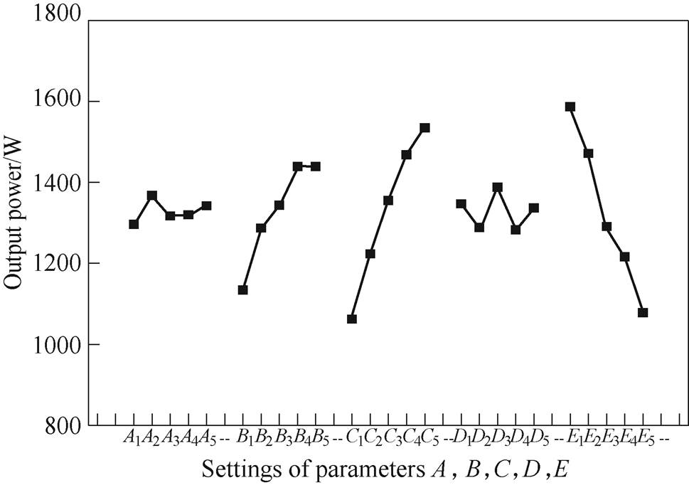
Fig.11 Plot of main factor effects on the output power
3.4.3 Analysis of variance (ANOVA)
An important purpose of ANOVA is to determine the relative importance of the various design variables. To conduct ANOVA, the sum of squares (SS) is calculated first. It is measure of the deviation of simulation data from the mean value of the data. The sum of squares (SSFA) due to various factors can be calculated as
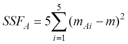 (10)
(10)SSFB, SSFC, SSFDand SSFE can be obtained in the same wsay. These results show in Tab.7.
Tab.7 Effects of all factors on characteristics analysis
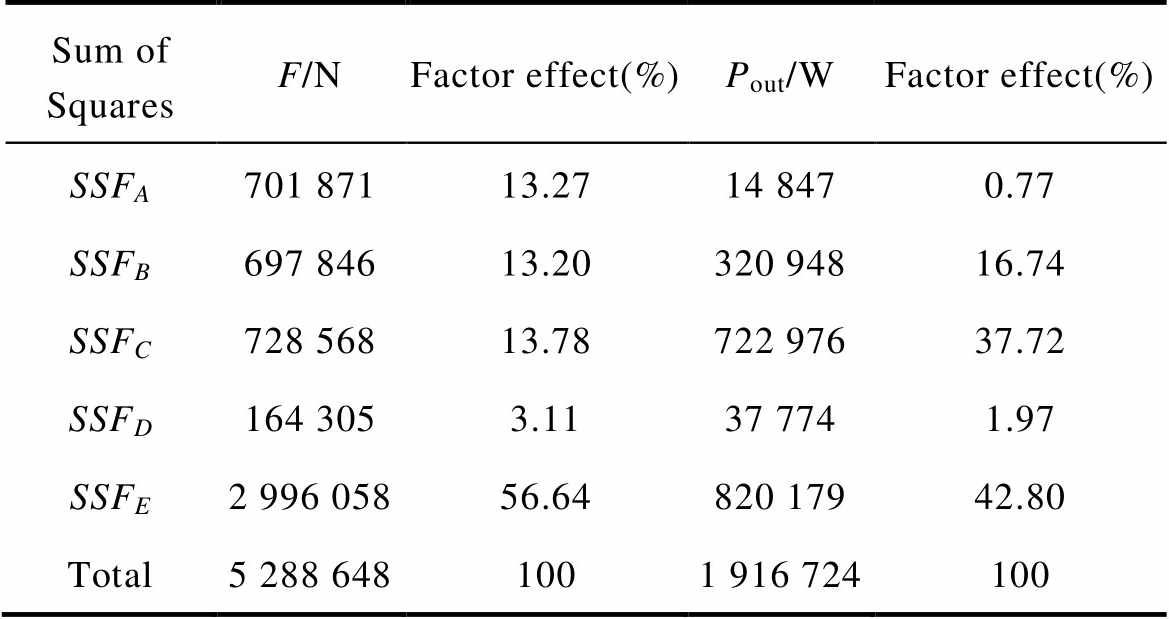
Sum of SquaresF/NFactor effect(%)Pout/WFactor effect(%) SSFA701 87113.2714 8470.77 SSFB697 84613.20320 94816.74 SSFC728 56813.78722 97637.72 SSFD164 3053.1137 7741.97 SSFE2 996 05856.64820 17942.80 Total5 288 6481001 916 724100
It is noted in Tab.5 and Fig.10 that the best combination of structure parameters for minimum the detent force is determined to be (A3, B2, C3, D5, E5). It is also noted in Tab.6 and Fig.11 that the best combination of structure parameters for maximum the output power is determined to be (A2, B4, C5, D3, E1). None of levels can be selected to constitute the elements of the optimum design for minimum the detent force and maximum the output power. All factors are used to regulate the values of detent force and output power. It is seen that in Tab.7, factors A, D and E has larger effect on detent force to output power. Factors B and C has larger effect on output power to detent force. Consequently, the best combination of structure parameters for minimum detent force and maximum output power is determined to be (A3, B4, C5, D5, E5).
To fully analyze the effectiveness of the Taguchi method, the optimal generator model of the 120°- TPMLG (optimal generator) are constructed based on best combination of structure parameters in the Tab.8, and its performance are analyzed and compared with those of the initial design model of the 120°-TPMLG (initial generator) and the traditional TPMLG. Fig.12a compares the no-load back electromotive force (EMF) under rated speed, where back-EMF waveforms of the three generators are almost sinusoidal. The correspon- ding spectral analysis results ars shown in Fig.12b. From the comparison it can be found that the fundamental amplitude of back-EMF waveforms for the optimal generator is 201.23V, which increase about 5.73% from the 190.33V for the initial generator. Besides, the fundamental amplitude of back-EMF waveform for the optimal generator is higher about 17.26% than that for the traditional TPMLG. The detent force of the three generators are shown in Fig.12c, it can be seen that the maximum detent force for the optimal generator is decreased to 187N from 1 150N for the initial generator, which represent 83.74% detent force is reduced. Additionally, the maximum detent force of the optimal generator is lower about 31.50% than that of the traditional TPMLG.
Tab.8 Comparison of combination
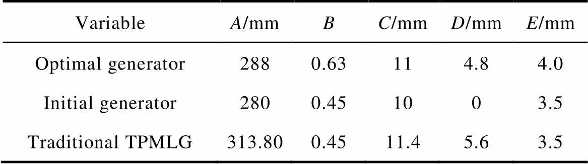
VariableA/mmBC/mmD/mmE/mm Optimal generator2880.63114.84.0 Initial generator2800.451003.5 Traditional TPMLG313.800.4511.45.63.5
The losses, output power and the efficiency of the three generators under rated operation are calculated and compared in Tab.9 and Fig.13.
Tab.9 Comparison of performance
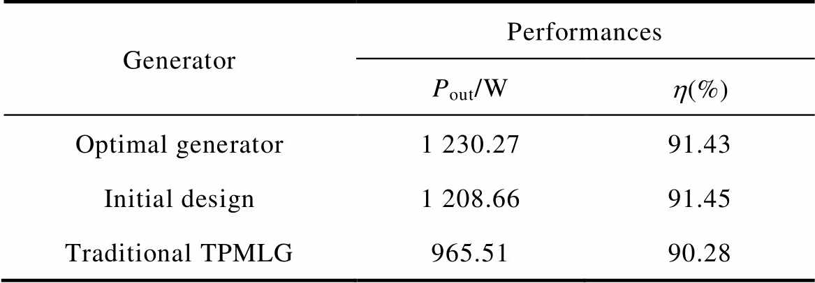
GeneratorPerformances Pout/Wh(%) Optimal generator1 230.2791.43 Initial design1 208.6691.45 Traditional TPMLG965.5190.28
As shown in Fig.13, the total losses of the three generators under the rated operation are 115.32W, 113.00W and 103.95W, respectively. Compared with the initial generator and traditional TPMLG, the total losses of the optimal generator are increased by 2.05% and 10.94%, respectively. Nevertheless, the output power of the optimal generator is increased by 1.78% and 27.42% than that of the initial generator and traditional TPMLG, respectively. The efficiency of the optimal generator and the initial generator are almost the same and are higher 1.15% than that of the traditional TPMLG.
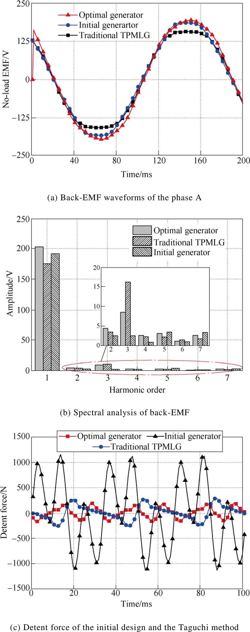
Fig.12 Performance of the initial and the Taguchi method
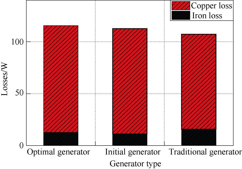
Fig.13 Losses of the three generators under the rated operation
This paper adopts the Taguchi method to optimize the structure parameters of the 120°- TPMLG for detent force reduction. The influence of different structural parameters on the detent force are analyzed via finite element method firstly. According to these analysis results, five optimization variables and their levels are determined. Meanwhile, the optimal design combined with the Taguchi method is conducted to minimize the detent force without losing output power. Finally, the optimal generator model is obtained and its performance is analyzed and compared with that of the initial generator and the traditional TPMLG. The results show that the detent force of the optimal generator is decreased by 83.74% and the output power increased by 1.78%. Therefore, it is effective to decrease the detent force of the 120°- TPMLG by this method.
Reference
[1] Trapanese M, Boscaino V, Cipriani G, et al. A per- manent magnet linear generator for the enhancement of the reliability of a wave energy conversion system[J]. IEEE Transactions on Industrial Electro- nics, 2019, 66(6): 4934-4944.
[2] Du Jinhua, Liang Deliang, Xu Longya, et al. Modeling of a linear switched reluctance machine and drive for wave energy conversion using matrix and tensor approach[J]. IEEE Transactions on Magnetics, 2010, 46(6): 1334-1337.
[3] Chen Hao, Zhan Yiming, Wang Haiying, et al. A tubular permanent magnet linear generator with novel structure[J]. IEEE Transactions on Plasma Science, 2019, 47(6): 2995-3001.
[4] Farrok O, Islam M R, Islam Sheikh M R, et al. Oceanic wave energy conversion by a novel per- manent magnet linear generator capable of preventing demagnetization[J]. IEEE Transactions on Industry Applications, 2018, 54(6): 6005-6014.
[5] Gao Yuping, Shao Shuangquan, Zou Huiming, et al. A fully floating system for a wave energy converter with direct-driven linear generator[J]. Energy, 2015, 95: 99-109.
[6] Jin Fuli, Si Jikai, Cao Zhiping, et al. Analysis of a six-phase direct-drive permanent magnet synchronous motor with novel toroidal windings[C]//16th IEEE Vehicle Power and Propulsion Conference (VPPC), Hanoi, 2019: 14-17.
[7] Cui Xu, Si Jikai, Feng Haicao, et al. Operating principle and electromagnetic characteristic analysis for large-small pole solid-rotor induction motor with toroidal windings[J]. Transactions of China Electro- technical Society, 2019, 34(9): 1850-1856.
[8] Gao Mengzhen, Si Jikai, Gao Caixia, et al. Cogging torque minimization in novel direct-drive PMSM with toroidal windings[C]//22nd International Conference on Electrical Machines and Systems (ICEMS), Harbin, 2019: 5108-5112.
[9] Chung S U, Kim J M. Double-sided iron core PMLSM mover teeth arrangement design for reduction of detent force and speed ripple[J]. IEEE Transactions on Industrial Electronics, 2016, 63(5): 3000-3008.
[10] Chu Wenqiang, Zhu Ziqiang. Investigation of torque ripples in permanent magnet synchronous machines with skewing[J]. IEEE Transactions on Magnetics, 2013, 49(3): 1211-1220.
[11] Hu Hengzai, Liu Xiangdong, Zhao Jing, et al. Analysis and minimization of detent end force in linear permanent magnet synchronous machines[J]. IEEE Transactions on Industrial Electronics, 2018, 65(3): 2475-2486.
[12] Kwon Y S, Kim W J. Detent-force minimization of double-sided interior permanent-magnet flat linear brushless motor[J]. IEEE Transactions on Magnetics, 2016, 52(4): 1-8.
[13] Hu Xiaofei, Liu Chao, Wang Yi, et al. Analysis and optimization of single phase brushless slotted limited-angle torque motor[J]. Transactions of China Electrotechnical Society, 2019, 34(13): 2744-2751, 1856.
[14] Anusha Vadde, Sudha B. Influence of skewing design for reduction of force ripples in DSL-SYNRM using 3D FEA[J]. China Electrotechnical Society Transa- ctions on Electrical Machines and System, 2019, 3(4): 397-402.
[15] Liu Guohai, Wang Yanyang, Chen Qian, et al. Multi- objective optimization of an asymmetric V-shaped. interior permanent magnet synchronous motor[J]. Transactions of China Electrotechnical Society, 2018, 33(2): 385-393.
[16] Gao Jian, Dai Litao, Zhang Wenjuan, et al. Improved genetic optimization algorithm with subdomain model for multi-objective optimal design of SPMSM[J]. China Electrotechnical Society Transactions on Elec- trical Machines and Systems, 2018, 2(1): 160-165.
[17] Guo Youquan, Si Jikai, Gao Caixai, et al. Improved fuzzy-based Taguchi method for multi-objective optimization of direct-drive permanent magnet syn- chronous motors[J]. IEEE Transactions on Magnetics, 2019, 55(6): 1-4.
[18] Hwang C C, Lyu L Y, Liu C T, et al. Optimal design of an SPM motor using genetic algorithms and Taguchi method[J]. IEEE Transactions on Magnetics, 2008, 44(11): 4325-4328.
[19] Li Xianglin, Li Jinyang, Yang Guangyong, et al. Multi-objective optimization analysis of electric- excitation double-stator field-modulated machine[J]. Transactions of China Electrotechnical Society, 2020, 35(5): 972-982.
[20] Zhu Huangqiu, Cheng Yifeng. Rotor optimization design of bearing less permanent magnet synchronous motor based on modular poles[J]. Electric Machines and Control, 2020, 24(3): 123-130.
[21] Cheng Peng, Yang Xinjiu, Lan Hai, et al. Design and efficiency optimization of a synchronous generator using finite element method and Taguchi method[J]. Electric Machines and Control, 2019, 23(2): 94-104.
[22] Si Jikai, Feng Haicao, Su Peng, et al. Design and analysis of tubular permanent magnet linear wave generator[J]. The Scientific World Journal, 2014, 65(9): 1-7.
[23] Liu Chunyuan, Yu Haitao, Hu Minqiang, et al. Detent force reduction in permanent magnet tubular linear generator for direct-driver wave energy conversion[J]. IEEE Transactions on Magnetics, 2013, 49(5): 1913- 1916.
[24] Tang Xu, Wang Xiuhe, Tian Mengmeng, et al. Study of reduction methods of cogging torque in line-start permanent magnet synchronous motor by changing the parameters of stator teeth and slots[J]. Transa- ctions of China Electrotechnical Society, 2016, 31(23): 1-8.
[25] Liu Chunyuan. Research on the tubular permanent magnet linear generator using direct driven wave power take off system[D]. Nanjing: Southeast University, 2015.
摘要 圆筒型永磁直线发电机(TPMLG)采用120°相带环型绕组可以提高其功率密度,然而,TPLMG具有较大的定位力,这会引起发电机的振荡甚至使系统不稳定。为了解决这一问题,该文对120°相带环形绕组(120°-TPMLG)的圆筒型永磁直线发电机进行优化设计。首先利用有限元方法研究不同结构参数(定子铁心长度、极弧系数、槽肩宽度、定子齿宽和气隙长度)对定位力的影响。根据分析结果,结合田口方法对发电机进行优化设计,在不损失输出功率的情况下使定位力最小,得到120°-TPMLG的最优结构参数。为了验证优化设计过程的有效性,将优化后的120°-TPMLG与初始发电机的性能进行比较。结果表明,优化后的120°-TPMLG的定位力得到了极大的减小,输出功率也略有增加。因此,该文采用的优化方法对减小120°-TPMLG的定位力是有效的。
关键词:120°相带环形绕组 定位力 优化设计 圆筒型永磁直线发电机 田口法
中图分类号: TM359.4
DOI: 10.19595/j.cnki.1000-6753.tces.201077
This work is partially supported Natural Science Foundation of China under grant No.51777060, in part by the Major Special Project for Collaborative Innovation in Zhengzhou No. 20XTZX12023.
Received August 30, 2020;
Revised October 12, 2020.
Notes Brief
Si Jikai born in 1973, PhD, Major research interests include the theory, application, and control of special motor design.E-mail: sijikai527@126.com
Yan Zuoguang born in 1995, Master Candidate, Major research interests include permanent magnet linear generator and applications.E-mail: yzg151231@126.com (Corresponding author)
(编辑 陈 诚)