 ,方波电压
,方波电压 、
、 和
和 的幅值为
的幅值为 、
、 和
和 ,电感的高频链电流为
 、
、 、
、 。
。 、
、 和
和 分别为各端口串联电感,
 为变压器励磁电感。
 为各端口的开关管,
 ,各端口对角开关互补导通。
摘要 三端口隔离三有源桥(TAB)DC-DC变换器作为新能源接入的一种积极探索与尝试,在分布式光伏接入、新能源汽车及多电压等级直流用电需求等领域得到了广泛关注。软开关能力作为TAB应用的关键优势之一,可以有效地降低开关损耗、提升变换效率。然而,由于开关管数量增多,TAB的工作模式及移相控制方法较双有源桥(DAB)DC-DC变换器出现了成倍增加的现象,现有DAB的零电压开通(ZVS)已不利于推广至TAB。该文在分析TAB工作原理的基础上,从开关管驱动信号出发,将TAB的等效电路进行了分解,构建双电源作用下电感电流的统一表达式。基于叠加定理,TAB每个开关管开通时刻的电感电流均可以由多个双方波电压源作用下的电感电流相加得到,并且不受移相控制方法的影响,计算简便。基于TAB等效电路的分解模型,该文绘制不同移相控制方法下TAB的全开关ZVS区域,并对其进行讨论分析。最后搭建实验平台,验证了该方法的可行性与有效性。
关键词:软开关 隔离式DC-DC变换器 电感电流 移相控制
随着能源问题的日益严峻,新能源的应用得到了广泛的关注和研究。由于新能源的间歇性、时变性和随机性等特点,在新能源系统中需储备储能单元对电能进行削峰填谷,进而实现对负载的连续稳定供电[1-3]。传统的新能源系统中,新能源发电单元、负载和储能单元由多个双向或单相的独立直流变换器进行连接,结构复杂、体积较大。采用三有源桥(Triple Active Bridge, TAB)取代多个独立变换器,不仅可以满足各个端口间能量的双向流动、电压匹配和电气隔离,还可以简化系统结构、减小装置质量和体积,提升整体变换效率[4-7]。目前,TAB已成为以上应用领域的研究热点之一。
相较于双有源桥(Dual-Active-Bridge, DAB)[8-10],TAB的很多研究工作还停留在初步的理论研究和探讨阶段,仍存在大量的理论和共性关键问题有待解决。DAB的控制策略有单移相(Single-Phase-Shift, SPS)、扩展移相(Extended-Phase-Shift, EPS)、双移相(Dual-Phase-Shift, DPS)和三重移相(Triple- Phase-Shift, TPS)。通过增加控制自由度,DAB可实现零电压开通(Zero Voltage Switching, ZVS)、无功环流和功率损耗的多目标优化。同样地,TAB在以上控制策略下,也存在ZVS区域。但由于端口数量增多,TAB的工作模式和控制自由度均大大增加。因此,DAB的模态分析法和分段线性法在应用到TAB时,其计算过程会较为复杂。
TAB的研究内容目前多关注各端口间的解耦、建模以及不同运行模式下的控制策略切换等方面,而针对TAB的软开关实现条件,还缺乏深入的分析和研究[11-12]。文献[11]提出了一种TAB的系统模型,并基于该模型给出了相应的优化控制方法,可提高能量从电网端口向储能端口流动时的转化效率。文献[12]构建了TAB的小信号模型并基于该模型设计了PI解耦控制器,该控制器可将TAB强耦合的各端口解耦为三个交流等效电路,进而降低了TAB的设计复杂性并提高了其动态响应特性。但以上文献均未考虑TAB的软开关特性。文献[13]基于傅里叶等效法,分析了DAB的ZVS边界条件,但是只考虑了电流的基波分量,忽略了谐波分量,在高频应用场合会有较大的误差。文献[14]提出了一种多谐振腔的三端口变换器,并考虑了方波电压的基频和三倍频分量进行端口高频链电流的计算,相较于只考虑基频的计算方法,其ZVS精度有所提高,但是该方法只适用于所提出的电路结构,不具有普适性。文献[15-17]基于傅里叶等效法分析了DAB多个工作模式下的ZVS区域,但主要考虑的是基波分量,忽略了谐波分量。文献[18]基于分段线性法,准确绘制了DAB不同工作模式下的ZVS区域,以此为基准,分析了傅里叶等效法在考虑不同谐波分量时其ZVS区域的误差。文献[19]基于分段线性法,对DAB在DPS控制下的四个工作模式进行了ZVS区域的求解,该方法可应用到TAB,但由于端口数量的增加,计算过程较为复杂。文献[20]基于分段线性法,分析了轻载状态时,DAB在TPS控制下的ZVS区域。文献[21]研究了三电平DAB的软开关特性,并对四种工作模式下的ZVS区域进行了分析,进而实现了DAB的多目标优化调制。可以发现,现有文献多是针对DAB的某一特定工作模式或特定移相控制方法下的多种工作模式进行分析研究,其分析方法有两种,即分段线性法和傅里叶等效法。分段线性法可以准确地绘制ZVS的区域,但需针对不同的工作模式或者移相控制策略分别进行计算。而且随着端口数量的增多,其计算过程非常繁琐、复杂。傅里叶等效法只能考虑有限级数的谐波分量,需在计算精度和计算复杂性之间做出权衡,并且需对不同的工作模式和移相策略分别进行推导和计算。因此,现有DAB的ZVS研究方法不利于推广至TAB的应用。基于此,文献[22]针对TAB构建了包含全部谐波分量的软开关准确模型,从而实现所有开关管的软开关参数设计,但是该方法仅适用于SPS控制,对于更为复杂的移相策略则不太适用。
TAB应用的关键优势之一就是其开关管的软开关能力。对于高压开关器件,实现所有开关管的ZVS是降低损耗的有效方式,也是提升变换效率的有效手段。本文以TAB为研究对象,采用叠加定理将多端口变换器分解为多个双电源共同作用的子电路,推导了子电路模型中开关管开通时电感电流的统一公式。最后由各子模型中电流的统一公式,构建了TAB各开关管开通时电感电流的统一公式,并根据开关管的ZVS边界条件,绘制了不同占空比下变换器的全开关ZVS区域。本文所提出的方法操作简便、准确度高,且不受工作模态和移相控制方法的影响,易于推广、可移植性强。
图1为本文研究的隔离式TAB变换器的拓扑结构,主要由三个电压源型H桥模块、电感和高频变压器组成。三绕组变压器电压比为,方波电压、和的幅值为、和,电感的高频链电流为、、。、和分别为各端口串联电感,为变压器励磁电感。为各端口的开关管,,各端口对角开关互补导通。

图1 TAB拓扑结构
Fig.1 Topology of TAB converter
TAB等效电路如图2所示。假设
 [23],图2a和图2b为TAB原始等效电路和折算到端口1的Y形等效电路。
 、
、 、
、 、
、 、
、 、
、 分别为端口2与端口3折算到端口1的方波电压、方波电压幅值大小及高频链电流,
 、
、 分别为端口2与端口3折算到端口1的等效电感。各变量的折算关系为
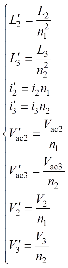 (1)
(1)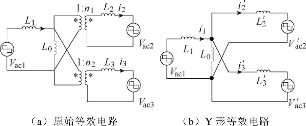
图2 TAB等效电路
Fig.2 Equivalent circuit of TAB converter
令 为开通时流过开关管的电流值,
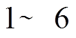 。变换器全开关管ZVS的条件为
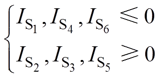 (2)
(2)以端口1的方波电压为参考,可以得到TAB在端口2和端口3移相角变化时的六种工作模式,如图3所示。图中, 、
、 分别为方波电压
 和
和 、和
、和 之间的移相角。
图3 TAB工作模式
Fig.3 Operation modes of TAB converter
参考DAB的控制方法, 为DAB端口1和端口2方波电压的占空比。则DAB在SPS、EPS、DPS和TPS控制下[24]的占空比关系分别为
 (3)
(3) (4)
(4)
 (5)
(5)
 (6)
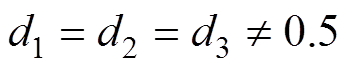
(6)以TAB为例, 为端口1、端口2和端口3方波电压的占空比,其占空比的组合关系为
 (7)
(7)
 (8)
(8) (9)
(9)
 (10)
(10)
 (11)
(11) (12)
(12)
 (13)
(13)
 (14)
(14)可以发现,其占空比组合方式比DAB多出一倍,工作模式为DAB的3倍。DAB的分段线性法或傅里叶等效法推广至TAB时,其计算过程会较为复杂繁琐。因此,迫切需要一个统一的表达式,可以直观地表示TAB的各个模态在不同占空比组合下的电流值。
图4为开关管的触发脉冲及各端口方波电压的波形, 。
。
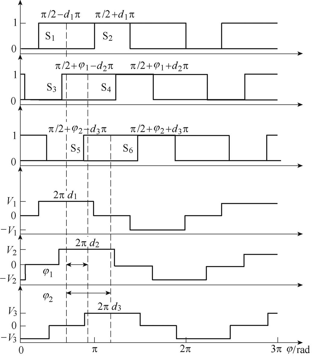
图4 TAB触发脉冲及方波电压
Fig.4 Pulses and square-wave voltages of TAB
可以发现,各触发脉冲均为占空比为0.5的统一方波,因此可考虑将各端口的电压拆解为与该端口触发脉冲相关的电压源。以端口1为例,可将端口1的方波电压分解为两个占空比为0.5、方向相反、幅值均为 的方波电压。两个方波电压相对于
 时刻的移相角与开关管
 、
、 触发脉冲同相位,分别为
 和
和 ,由此可得图5所示的TAB电路分解。
 =
= ,即对应开关管触发脉冲的等效电压源,
 ~
~ 同理,图5所示的TAB电路分解中移相角的数学关系为
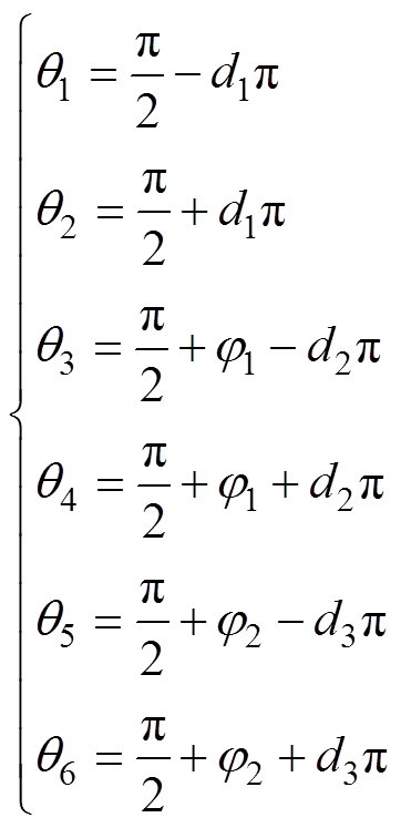 (15)
(15)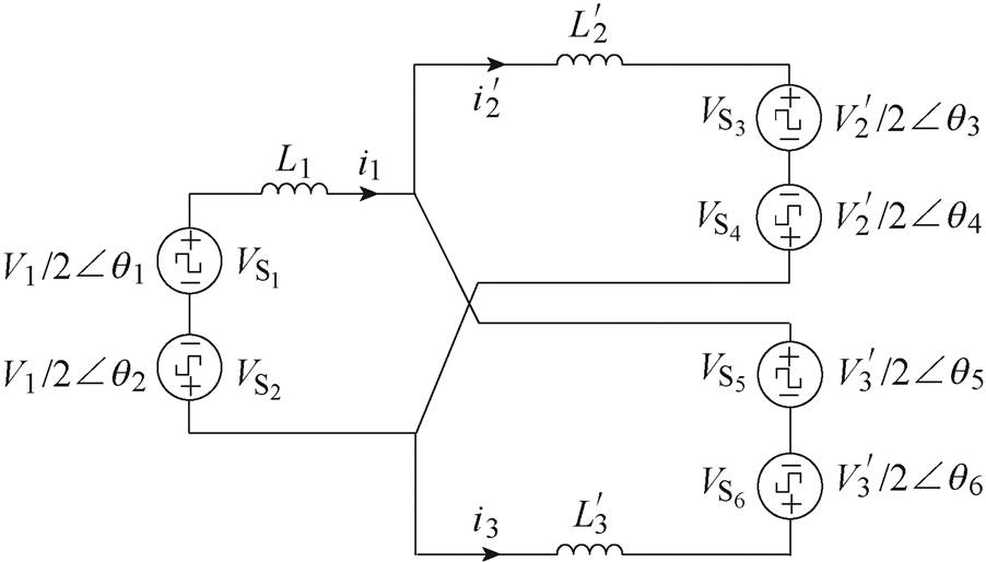
图5 TAB电路分解
Fig.5 Circuit decomposing of TAB
端口1和端口2在两个方波电压源作用下串联电感 的电压电流波形如图6所示。
 为端口1方波电压的幅值,
 为端口2折算到端口1的方波电压幅值,
 为两个端口电压间的移相角。根据伏安平衡关系可知,电感电流拐点值的关系如图6所示。由分段线性法可得
 (16)
(16)式中, 为开关频率。
图6 双电源电路的电压电流波形
Fig.6 Voltage and current waveforms of dual voltage source circuit
两个方波电源作用下电流的统一公式为
 (17)
(17)式中,为相位基准侧在电感端等效电压的幅值; 为另一个计算电源在电感端等效电压的幅值。基于本节中的统一公式(17)及对其各个变量的理解,可考虑将图5中的TAB电路进一步分解为多个双电源作用的子电路。为计算端口1开关管开通时刻的电流,可将TAB的电路以的触发脉冲为相位基准分解模型如图7所示。
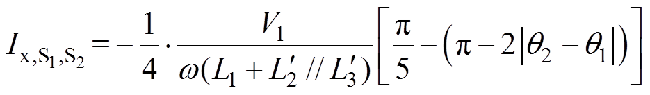
根据图7可得 的表达式为
的表达式为
 (18)
(18)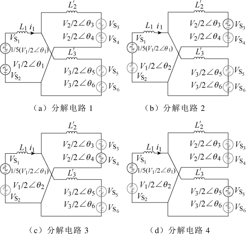
图7  的电路分解模型
Fig.7 Circuit decomposing for calculation
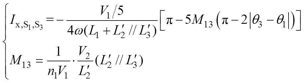
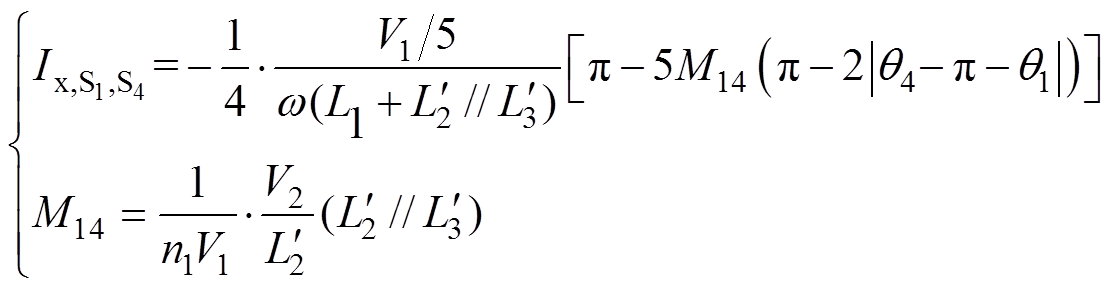
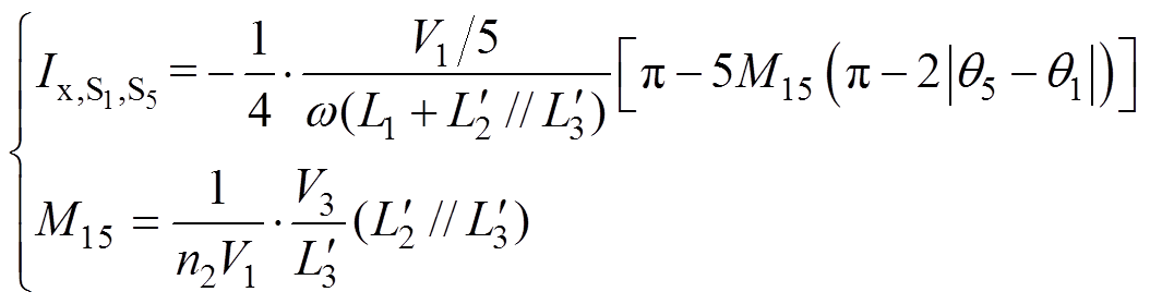
式中,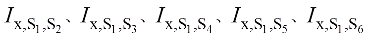 为开关管对应的等效电源分别与开关管~
 对应的等效电源共同作用下开通时刻的电流,即图7a~图7e子电路。由图7及式(17),根据戴维南定理,可直观地得到
 (19)
(19) (20)
(20)
 (21)
(21)
 (22)
(22) (23)
(23)
由此可知
 (24)
(24)令 ,
, 则
则
 (25)
(25)
同理,若以其他开关管的触发脉冲作为相位基准,则可以得到其他开关管开通时刻的电流即 ~
~ 。不同相位基准时,各开关管移相角的数学关系见表1。基于电路的对称性,可根据式(25)及表1写出
 (26)
(26) (27)
(27)
表1 不同相位基准时驱动信号相关电压的移相角
Tab.1 Phase shift angle of the switches at different phase reference
驱动信号相位基准 j =0q1q2q3q4q5q6 S10q2-q1q3-q1q4-p-q1q5-q1q6-p-q1 S2q1-q20q3-(q2-p)q4-q2q5-(q2-p)q6-q2 S3q1-q3q2-p-q30q4-q3q5-q3q6-p-q3 S4q1-(q4-p)q2-q4q3-q40q5-(q4-p)q6-q4 S5q1-q5q2-p-q5q3-q5q4-p-q50q6-q5 S6q1-(q6-p)q2-q6q3-(q6-p)q4-q6q5-q60
 (28)
(28)假设各端口电感参数对称,即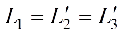 ,则
,则 之间的关系满足
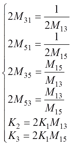 (29)
(29)
 ~可用
~可用 表示,进一步化简为
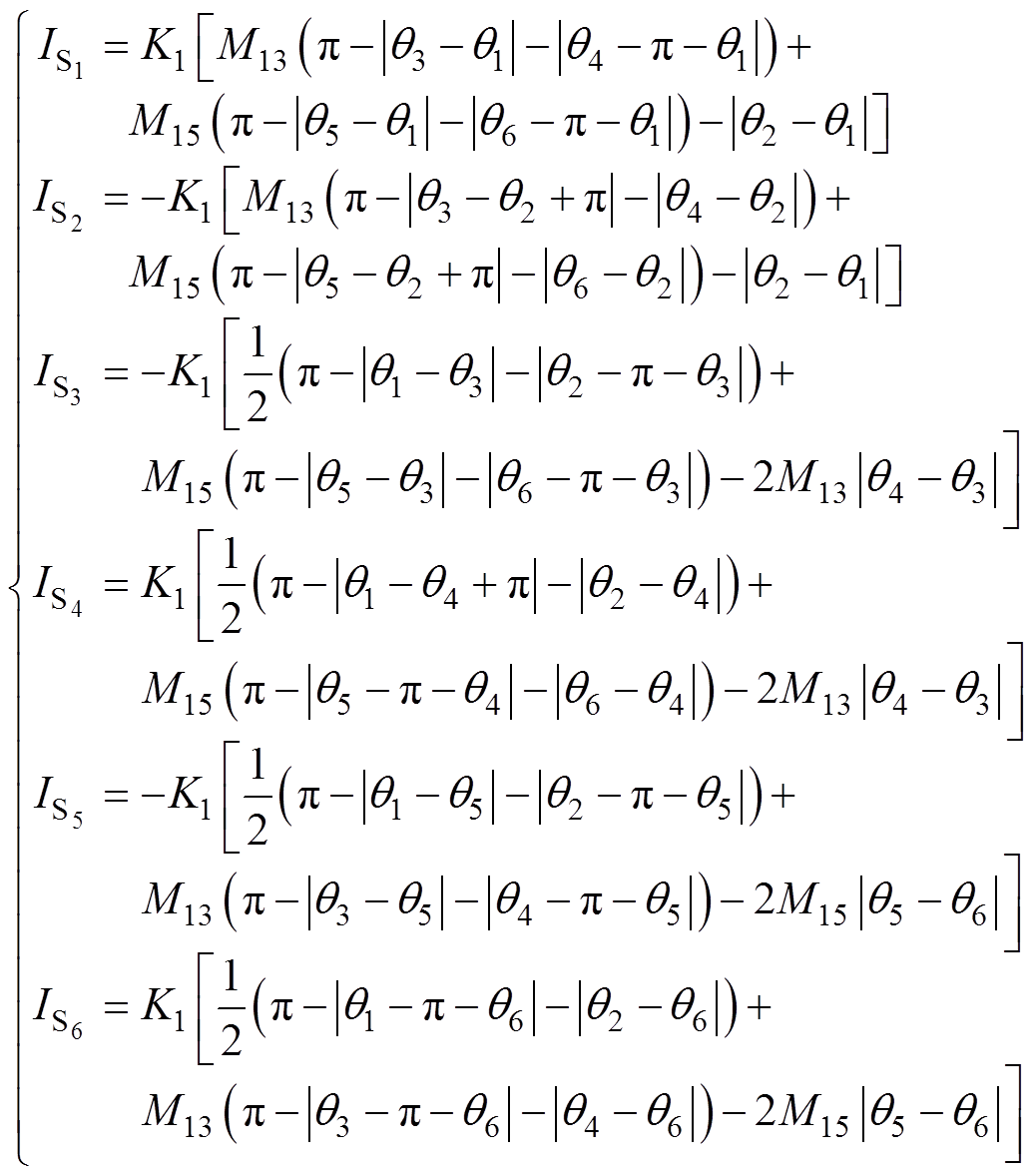 (30)
(30)
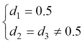
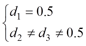
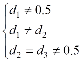
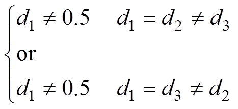
取式(7)~式(14)中典型的四种占空比关系为
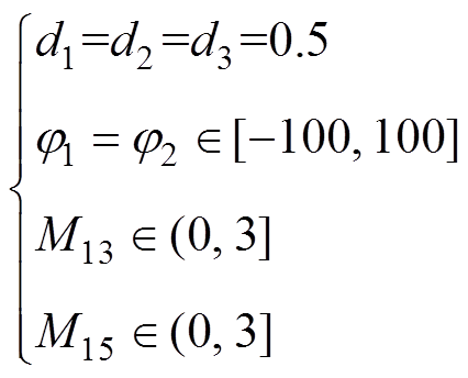 (31)
(31)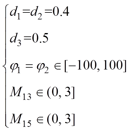 (32)
(32)
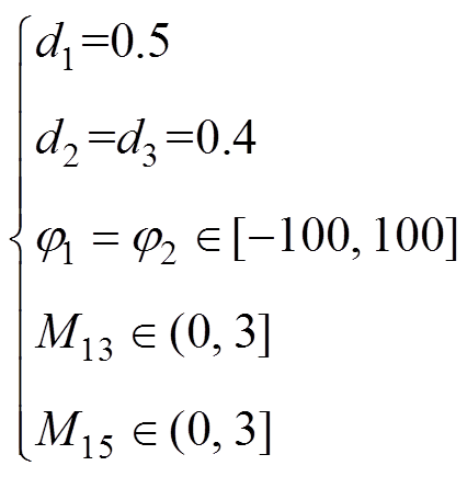 (33)
(33)
 (34)
(34)结合式(2)和式(30)可得不同移相控制下的全开关ZVS区域如图8所示。式(31)对应的三维ZVS区域如图8a所示,二维ZVS区域如图8b所示。式(32)~式(34)以此类推。三个端口方波电压的占空比均为0.5时,其ZVS区域关于 对称。不同占空比下变换器的全开关ZVS区域差别较大。当某端口方波电压的占空比为0.5时,该端口开关管的ZVS区域重合,而当占空比偏离0.5时,端口开关管的ZVS边界线出现了偏离,并彼此相交。因此,准确绘制TAB的ZVS区域对于变换器的优化设计具有实际意义。从推导过程可以看出,TAB的ZVS区域与各端口的电压及电感参数没有关系,仅与电压比
 及开关管的占空比和移相角相关。因此,通过合理选择电压比及移相控制方法,可在满足全开关管ZVS的同时实现多个目标的同步优化。
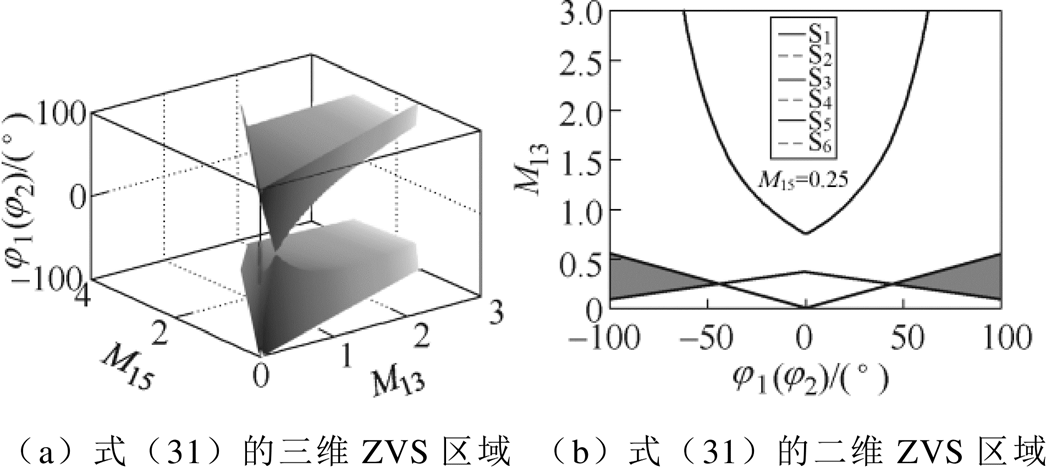
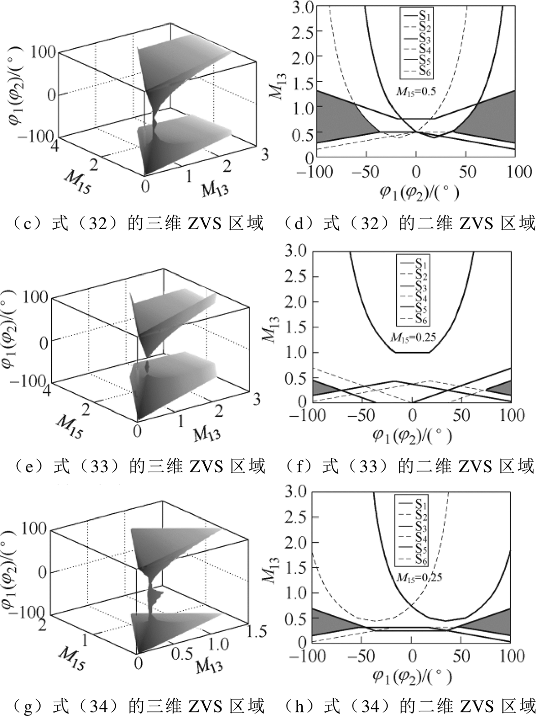
图8 不同移相控制下的全开关ZVS区域
Fig.8 ZVS area for all switches under different phase shift control
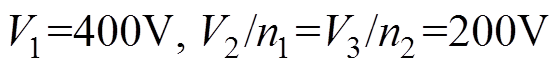
为验证图8中不同占空比下全开关ZVS区域的有效性,本文基于RT-Lab实验平台开展了实验验证,实验结果如图9~图16所示。
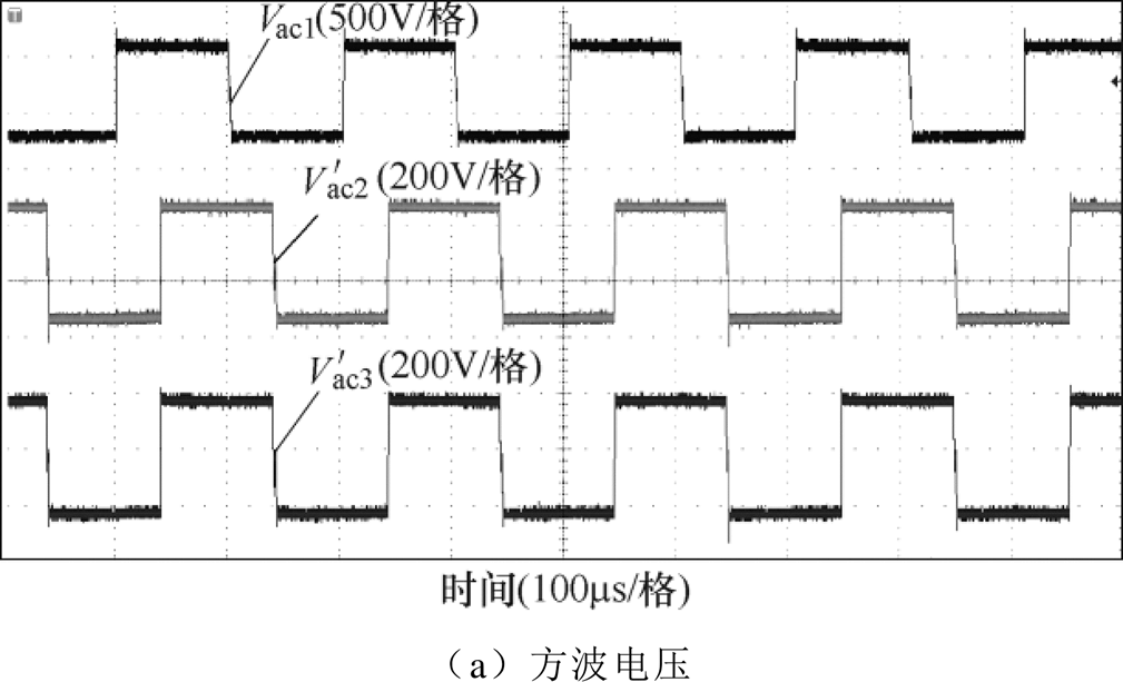

图9 实验1波形
Fig.9 The waveforms of experiment 1
实验1参数如下:
 。
。
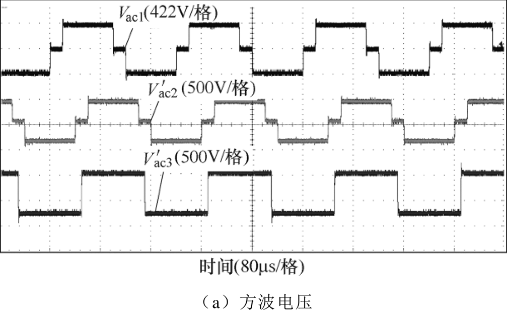

图10 实验2波形
Fig.10 The waveforms of experiment 2
 时,该参数下TAB全开关ZVS区域如图8b所示。令
 ,满足图8b中的ZVS边界。各开关管脉冲信号及端口电流波形如图9所示,各开关管均能满足式(2)所示的软开关条件。
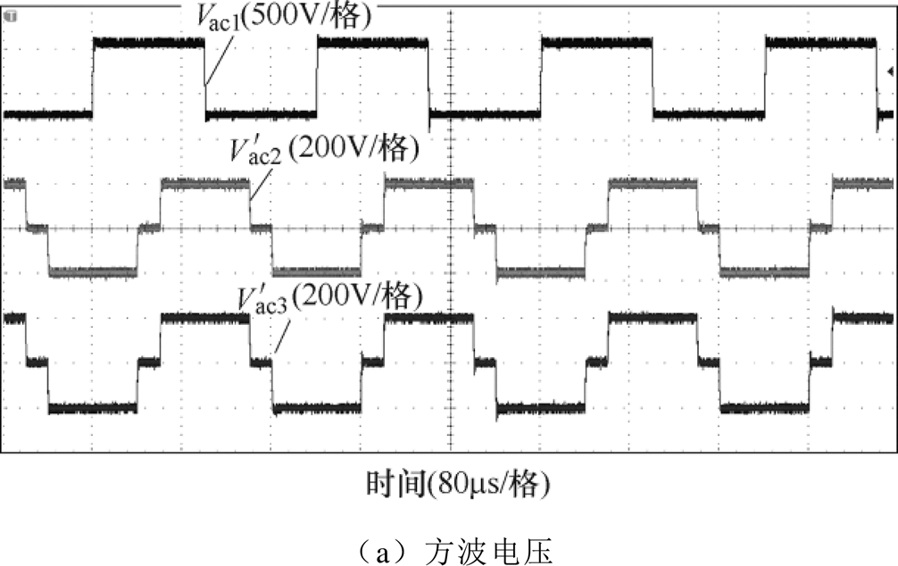

图11 实验3波形
Fig.11 The waveforms of experiment 3
实验2参数如下:
 ;
; ;
; ;
; 。
。
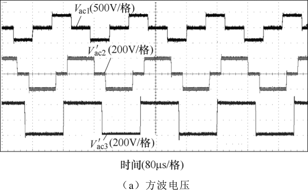

图12 实验4波形
Fig.12 The waveforms of experiment 4
 时,该参数下TAB全开关ZVS区域如图8d所示。令
 ,满足图8d中的ZVS区域。各开关管脉冲信号及端口电流波形如图10所示,各开关管均能满足式(2)所示的软开关条件。
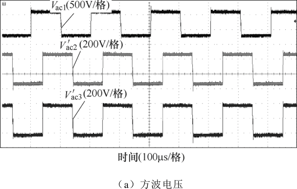
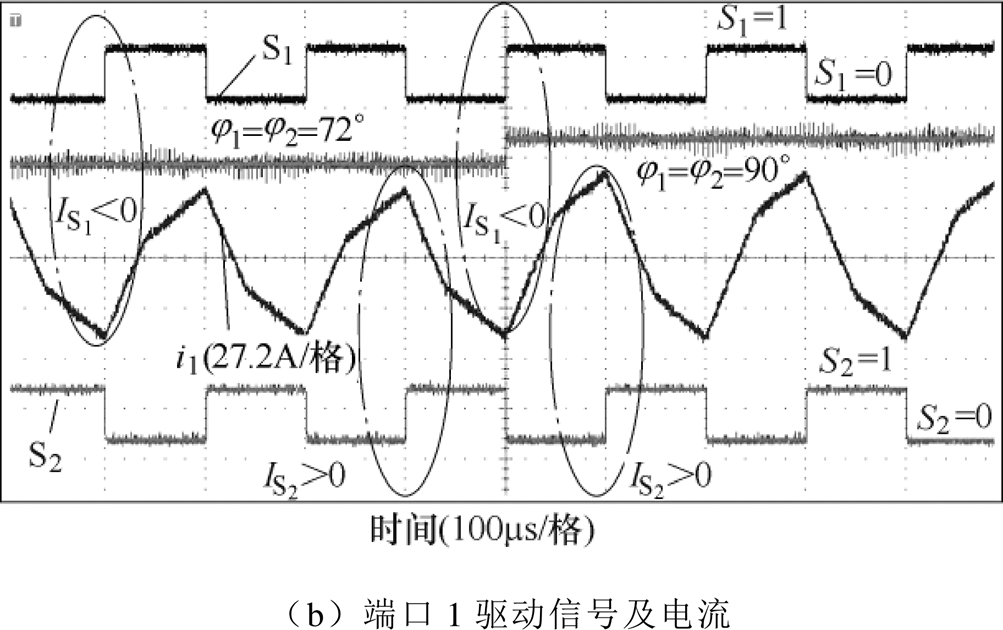
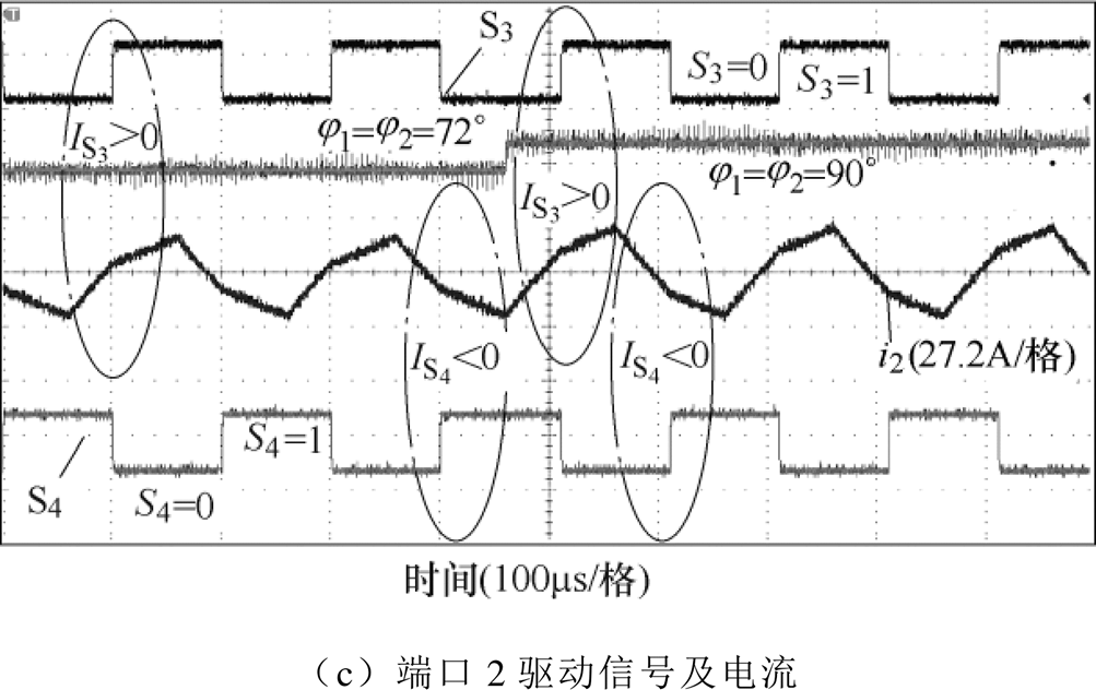
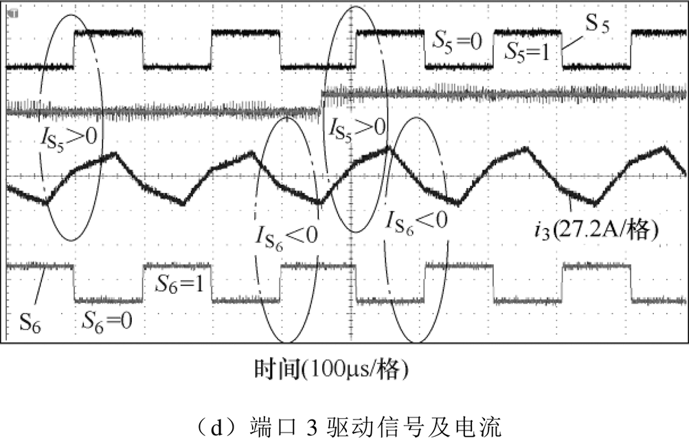
图13 实验1动态波形
Fig.13 The dynamic waveforms of experiment 1

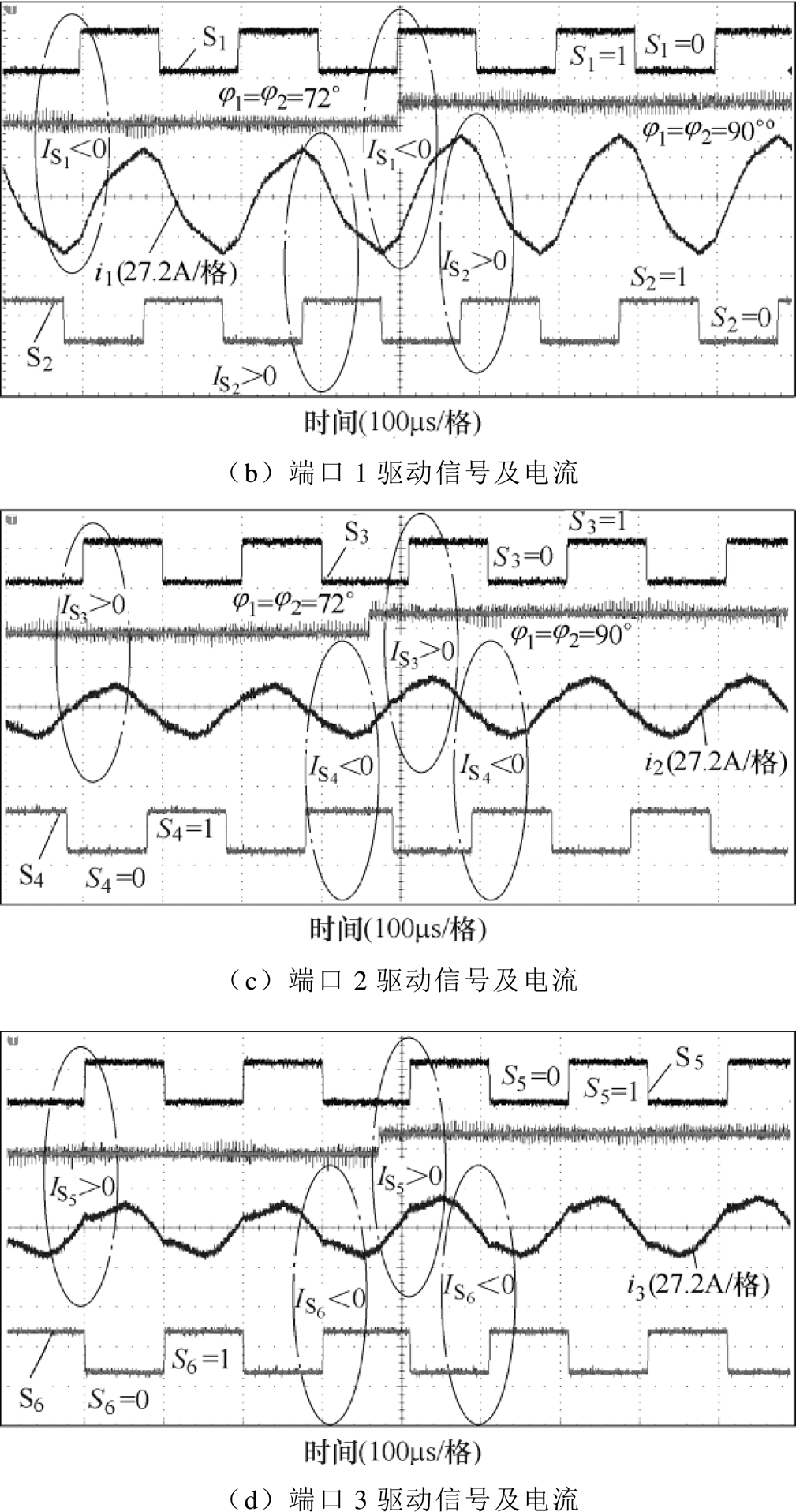
图14 实验2动态波形
Fig.14 The dynamic waveforms of experiment 2
实验3参数如下: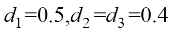 ;;;
;;; 。
。
 时,该参数下TAB全开关ZVS区域如图8f所示。令
 ,满足图8f中的ZVS区域。各开关管脉冲信号及端口电流波形如图11所示,各开关管均能满足式(2)所示的软开关条件。
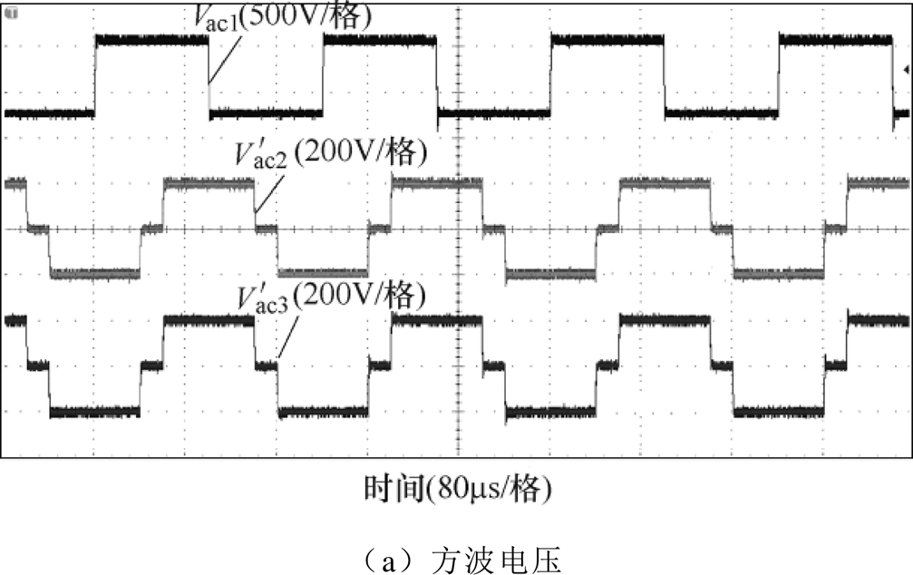
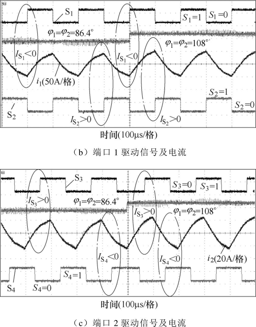
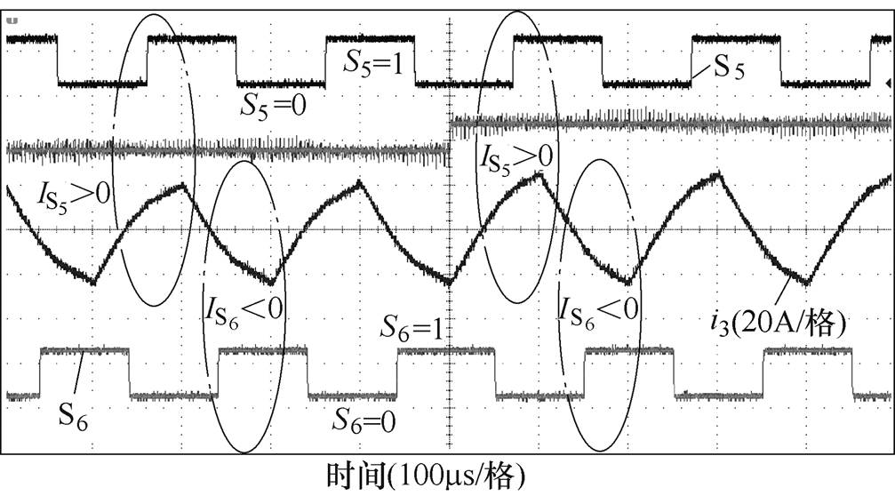
图15 实验3动态波形
Fig.15 The dynamic waveforms of experiment 3
实验4参数如下: ;;。
;;。
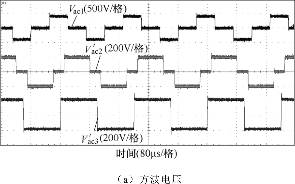
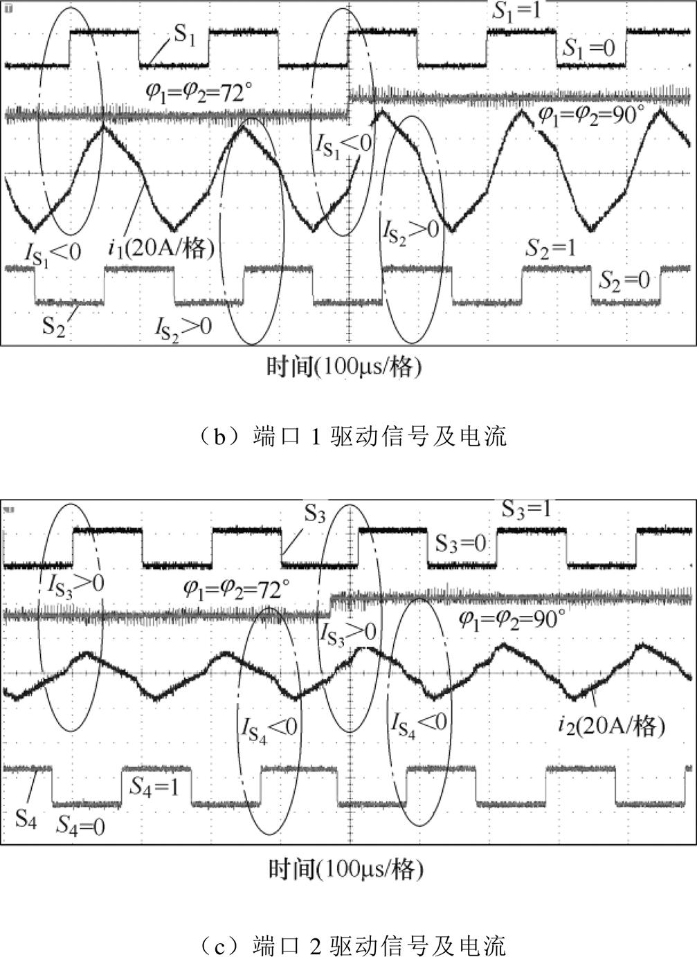
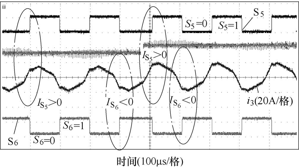
图16 实验4动态波形
Fig.16 The dynamic waveforms of experiment 4
时,该参数下TAB全开关ZVS区域如图8h所示。令,满足图8h中的ZVS区域。各开关管脉冲信号及端口电流波形如图12所示,各开关管均能满足式(2)所示的软开关条件。
理论上, 和
和 在ZVS区域动态变化时,TAB各端口的开关管仍能满足ZVS。实验1、实验2和实验4中,及
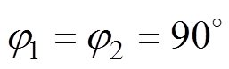 均在其ZVS区域中,实验3中,及
 均在其ZVS区域内。实验1、实验2中移相角由
 跳变到
跳变到 的动态波形如图13、图14所示;实验3中移相角由
 跳变到
跳变到 的动态波形如图15所示;实验4中移相角由跳变到的动态波形如图16所示。可以发现,理论分析与实验波形一致,移相角在ZVS区域动态变化时,全开关管ZVS仍可满足。
本文针对TAB全开关管的软开关特性,从各端口驱动信号出发,将各端口的方波电压以开关管相位为参考,分解为多个幅值相同、相位不同的0.5占空比的方波电压。基于叠加定理,本文将TAB的等效电路分解为多个双电源作用的子电路,并推导出子电路中开关管开通时电感电流的统一表达式。最后由多个子电路中电感电流的叠加即可得到特定开关管开通时的电流。不同于DAB电感电流的分段线性计算方法和傅里叶等效法,本文提出的方法计算简便、不受移相控制方法的影响,可直接得到所有占空比下TAB全开关管的ZVS区域。最后,基于RT-Lab实验平台,验证了本文所提方法的正确性和有效性,并得到以下结论:
1)TAB的ZVS区域与各端口的电压电感参数无关,仅与电压比 以及开关管的占空比和移相角相关。因此,准确绘制TAB的ZVS区域对于TAB的优化设计具有实际意义。
2)TAB某端口方波电压的占空比为0.5时,该端口开关管的ZVS区域重合,当占空比偏离0.5时,该端口开关管的ZVS区域相互偏离并且相交。因此,当移相角和电压比相同,端口方波电压占空比均为0.5时,TAB的ZVS区域最大。
参考文献
[1] 盛逸标, 林涛, 陈宝平, 等. 面向新能源外送系统次/超同步振荡的控制器参数协调优化[J]. 电工技术学报, 2019, 34(5): 983-993.
Sheng Yibiao, Lin Tao, Chen Baoping, et al. Coor- dination and optimization of controller parameters for subsynchronous/super-synchronous oscillation in new energy delivery systems[J]. Transactions of China Electrotechnical Society, 2019, 34(5): 983-993.
[2] 李梦柏, 谢竹君, 林卫星, 等. 一种适用于新能源并网的高增益单向直流变压器[J]. 电工技术学报, 2018, 33(2): 301-309.
Li Mengbo, Xie Zhujun, Lin Weixing, et al. Cascaded LC-AC transformer unidirectional DC-DC converter with high stepping ratio[J]. Transactions of China Electrotechnical Society, 2018, 33(2): 301-309.
[3] 王会超, 秦昊, 周昶, 等. 计及新能源预测不确定性的跨区域日前—日内调度模型[J]. 电力系统自动化, 2019, 43(19): 60-67.
Wang Huichao, Qin Hao, Zhou Chang, et al. Cross- regional day-ahead to intra-day scheduling model considering forecasting uncertainty of renewable energy[J]. Automation of Electric Power Systems, 2019, 43(19): 60-67.
[4] Duarte J, Hendrix M, Simoes M. Three-port bidire- ctional converter for hybrid fuel cell systems[J]. IEEE Transactions on Power Electronics, 2007, 22(2): 480-487.
[5] Krishnaswami H, Mohan N. Three-port series- resonant DC-DC converter to interface renewable energy sources with bidirectional load and energy storage ports[J]. IEEE Transactions on Power Electronics, 2009, 24(10): 2289-2297.
[6] Bhattacharjee A K, Kutkut N, Batarseh I. Review of multi port converters for solar and energy storage integration[J]. IEEE Transactions on Power Electro- nics, 2019, 34(2): 1431-1445.
[7] 余雪萍, 涂春鸣, 肖凡, 等. 三端口隔离DC-DC变换器的暂态直流偏置机理及抑制策略[J]. 电工技术学报, 2020, 35(9): 1962-1972.
Yu Xueping, Tu Chunming, Xiao Fan, et al. Transient dc bias mechanism and suppression strategy of the three-port isolated DC-DC converter[J]. Transactions of China Electrotechnical Society, 2020, 35(9): 1962- 1972.
[8] 李婧, 袁立强, 谷庆, 等. 一种基于损耗模型的双有源桥DC-DC变换器效率优化方法[J]. 电工技术学报, 2017, 32(14): 66-76.
Li Jing, Yuan Liqiang, Gu Qing, et al. An efficiency optimization method in dual active bridge DC-DC converter based on loss model[J]. Transactions of China Electrotechnical Society, 2017, 32(14): 66-76.
[9] Zhao Biao, Song Qiang, Liu Wenhua, et al. Transient DC bias and current impact effects of high- frequency-isolated bidirectional DC-DC converter in practice[J]. IEEE Transactions on Power Electronics, 2016, 31(4): 3203-3216.
[10] 魏腾飞, 王晓兰, 李晓晓. 双向直流隔离变换器功率回流的分析及消除[J]. 电机与控制学报, 2019, 23(11): 100-108,117.
Wei Tengfei, Wang Xiaolan, Li Xiaoxiao. Analysis and elimination backflow power in bidirectional DC-DC isolation converter[J]. Electric Machines and Control, 2019, 23(11): 100-108,117.
[11] Zou Shenli, Lu Jiangheng, Alireza Khaligh. Modeling and control of a triple active bridge converter[J]. IET Power Electronics, 2020, 13(5): 961-969.
[12] Ishita Biswas, Debaprasad Kastha, Prabodh Bajpai. Small signal modeling and decoupled controller design for a triple active bridge multiport DC-DC converter[J]. IEEE Transactions on Power Electronics, 2020, DOI:10.1109/TPEL.2020.3006782.
[13] Li Xiaodong, Bhat A K S. Analysis and design of high-frequency isolated dual-bridge series resonant DC/DC converter[J]. IEEE Transactions on Power Electronics, 2010, 25(4): 850-862.
[14] 李微, 王议锋, 韩富强, 等. 一种隔离型三端口双向LCLC多谐振直流变换器[J]. 电工技术学报, 2018, 33(14): 3231-3244.
Li Wei, Wang Yifeng, Han Fuqiang, et al. An isolated three-port bidirectional LCLC multi-resonant DC-DC converter[J]. Transactions of China Electrotechnical Society, 2018, 33(14): 3231-3244.
[15] Everts J, Krismer F, Jeroen V D K, et al. Optimal ZVS modulation of single-phase single-stage bidire- ctional DAB AC-DC converters[J]. IEEE Transa- ctions on Power Electronics, 2014, 29(8): 3954-3970.
[16] Everts, Jordi. Closed-form solution for efficient ZVS modulation of DAB converters[J]. IEEE Transactions on Power Electronics, 2016: 7561-7576.
[17] Li Xiaodong, Bhat A K S. Analysis and design of high-frequency isolated dual-bridge series resonant DC/DC converter[J]. IEEE Transactions on Power Electronics, 2010, 25(4): 850-862.
[18] Riedel J, Holmes D G, Mcgrath B P, et al. ZVS soft switching boundaries for dual active bridge DC-DC converters using frequency domain analysis[J]. IEEE Transactions on Power Electronics, 2017, 32(4): 3166-3179.
[19] Hu Yan, Zhang Yu, Chen Qing, et al. Efficiency evaluation for DAB converter with reactive power minimization strategy and full ZVS operation[C]// 2019 IEEE Energy Conversion Congress and Expo- sition (ECCE), Baltimore, 2019: 4274-4280.
[20] 黄珺, 王跃, 李卓强, 等. 基于三重移相控制的双主动全桥直流变换器优化调制策略[J]. 中国电机工程学报, 2016, 36(6): 1658-1666.
Huang Jun, Wang Yue, Li Zhuoqiang, et al. Optimized modulation scheme of dual active bridge DC-DC converter based on triple-phase-shift control[J]. Proceedings of the CSEE, 2016, 36(6): 1658-1666.
[21] 童安平, 邵持, 杭丽君, 等. 混合三电平DAB变换器软开关分析与多目标优化调制技术研究[J]. 中国电机工程学报, 2020, 40(24): 8098-8110.
Tong Anping, Shao Chi, Hang Lijun, et al. Investigation on soft switching characteristics and the multi-objective optimized modulation strategy for hybrid three-level DAB converter[J]. Proceedings of the CSEE, 2020, 40(24): 8098-8110.
[22] 田昕, 王聪, 沙广林, 等. 三端口直流变换器软开关分析的一种准确模型[J]. 电源学报, 2020, 18(4): 94-101.
Tian Xin, Wang Cong, Sha Guanglin, et al. An accurate model for soft-switching analysis of three- port DC-DC converter[J]. Journal of Power Supply, 2020, 18(4): 94-101.
[23] Zhao Chuanhong, Round S D, Kolar J W. An isolated three-port bidirectional DC-DC converter with decoupled power flow management[J]. IEEE Transactions on Power Electronics, 2008, 23(5): 2443-2453.
[24] 赵彪, 宋强. 双主动全桥DC-DC变换器的理论和应用技术[M]. 北京: 科学出版社, 2017.
Soft Switching Characteristics of the Three-Port Isolated DC-DC Converter
Abstract As an active exploration, the triple active bridge (TAB) has been widely concerned in the fields of distributed photovoltaic access, new energy vehicles, and multi-voltage level DC power demand. Soft switching is one of the key advantages of TAB, which can effectively reduce switching loss and improve conversion efficiency. However, due to the increase in the number of switches, the working mode and phase shift control method of TAB have multiplied compared with the dual active bridge (DAB), and the existing ZVS method of DAB is not applicable to TAB. Based on the analysis of TAB working principle, the equivalent circuit of TAB is decomposed from switching signals, and the uniform expression of the inductor current under dual-power supply is constructed. According to the superposition theorem, the inductor current at the opening time of certain switch can be obtained by adding the inductor current under multiple dual-power supplies. Moreover, it is not affected by the phase shift method, and the calculation is simple. Based on the decomposition circuit model, this paper draws and analyzes the ZVS region of TAB under different phase shift control methods. Finally, an experimental platform is built to verify the feasibility and effectiveness of the proposed method.
keywords:Soft switching, isolated DC-DC converter, inductor current, phase shift control
DOI: 10.19595/j.cnki.1000-6753.tces.200963
中图分类号:TM46
国家重点研发计划资助项目(2018YFB0904100)。
收稿日期 2020-08-01
改稿日期 2020-09-26
余雪萍 女,1990年生,博士研究生,研究方向为多端口直流变换器等。E-mail: Xuepingyu@163.com(通信作者)
涂春鸣 男,1976年生,博士,教授,主要研究方向为电能质量与控制、电力电子技术在电力系统中的应用等。E-mail: chunming_tu@263.net
(编辑 陈 诚)