
Fig.1 DC traction system
Abstract Stray current causes inevitable corrosion to structures near electric transportation systems, especially in DC urban rail transit. The paper considers the issue of stray current mitigation discussing what can be done for design and existing systems, sticking to applicable standards and consolidated protection practice. Mitigation measures may be devised for a new constructed system, such as the optimization of traction substation positions, reducing the longitudinal resistance of the running rails and return circuit, and using an additional stray current collection system (to be included in the track bed during construction). As for an existing system, besides increasing the total cross section of the aforementioned return circuit and stray current collection system by adding parallel conductors or cross-bonds, it is recommended to employ static converter units (e.g. negative resistance converters) to control the stray current in the return circuit. These units can be deployed in specific points where analysis or measurement indicates the large rail potential or incipient corrosion is spotted out.
Keywords: Urban rail transit, stray current, corrosion, stray current collection, stray current mitigation, negative resistance converter
Stray current corrosion poses challenges for the installations and structures exposed to free geo- magnetic currents and more remarkably to industrial electric processes and sources with significant leakage through soil[1-3]. As known, DC systems have a much higher impact than AC systems for the same amount of leakage[4]. High-voltage DC systems can affect buried structures near their earthing electrodes. Industrial processes such as welding, electrical discharge machining and galvanic plating also employ a large amount of current with significant dispersion through the installation and respective protection earthing circuits. However, the most relevant source of stray current both in terms of intensity and physical extension are electric transportation systems (ETSs), such as railways, metros, and tram lines. The peculiar element promoting a significant exchange of current with soil are the running rails, used as part of the traction supply return circuit and subject to significant degradation of the electrical interface throughout service life[5]. This, in combination with the integration of such transportation systems in the urban and suburban context, has made necessary a thorough analysis of the problem and of existing and preferable design solutions. The stray current problem is complex for the large extension of the system, the non-ideal electrical conditions at interfaces, the long- time interval for effects to become evident, and in general the interaction of multiple phenomena and disciplines (civil engineering, electrical engineering, chemistry), for which the word “holistic” was also used in an attempt to comprehend the various approaches[6].
Modeling and simulation always imply some degree of approximation, especially considering use of simplified circuits, the variability of parameters, and the combination of electrical and electrochemical phenomena[7]. In addition, results are not always fully and/or directly applicable, and a tradeoff with a wide range of constraints is always necessary. For example, the position of traction substations is subject to many constraints, and cannot follow the indications of a full optimization. Or the track-bed insulation is subject to structural constraints for the static and most of all dynamic response at train passage, especially at curves. In addition, construction pursues the goal of cost minimization, often offsetting costs to a later project stage and to maintenance (in charge of a different entity, the operator, in lieu of the original client). In general, the importance must be underlined of solutions that can be applied to already built systems, as part for instance of a major overhaul or upon evidence of critical damage and need of urgent intervention.
This paper thus offers an overview of solutions at construction and operation phase in an engineering perspective. The objective is the integration of stray current mitigation measures with construction exigencies and constraints and electrical safety constraints, carrying out a comparison with simple, yet representative, models.
For corrosion to occur, the formation of a corrosion cell is a necessity. It is composed of typically four components: anode, cathode, electrolyte and metallic path. Anode is where oxidation (removal of electrons) takes place. Cathode is where reduction (gain of electrons) takes place. Electrolyte is an electrically conductive solution, through which positively charged ions (cations) can flow. Conversely, a metallic path is necessary for the flow of electrons. Conventional current flows from anode to cathode in form of positively charged ions through the electrolyte; metallic path is necessary for the flow of electrons flow[8]. The best way to stop corrosion is opening this circuit by removing one (or more than one) of the aforementioned components of the corrosion cell.
The traction current, which in conjunction with the voltage applied to the collectors, supplies power to the railway traction vehicle through positive conductor (third rail or overhead contact system) must have a return path. As the current path must be considered to constitute a closed loop, the total return current must be equal to the current flowing through the positive conductor.
The train current collection devices receive the DC supply required to operate the train and the current then returns to traction substations via the wheels of the train and the unearthed rail track system.
Fig.1 illustrates that the third rail is positive with respect to the rails. Ideally, all the current should return through the rails. But due to the resistances of running rails and insulation deterioration between running rails & track plinth/slab, there will be a portion of the return traction current that deviates from the intended path (i.e. running rails) called stray current. This current leaks from the rails to the structure (track plinth, deck and surrounding ground), and flows back into the rectifier negative bus through the running rails. Since the rectifier is insulated from the earth, so there is no other path for stray current to enter the negative bus of the rectifier.
Fig.1 DC traction system
The return traction current causes a longitudinal voltage drop along the rails. Although the rails are isolated from the main mass of earth, there is inevitably distributed leakage resistance causing a varying potential difference with respect to earth[9]. Thus, the region where current leaving the metallic object (running rails, structure reinforcement, etc.) is the anodic region. The below reaction indicates the oxidation of iron which leads to corrosion[10].
Anodic reaction:
Cathodic reaction:
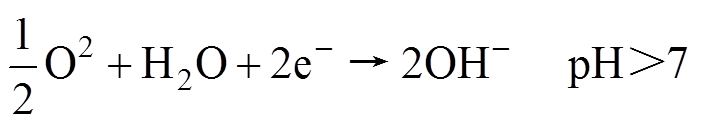
At the point where the stray current leaves the metal surfaces, an anodic reaction takes place at the metal/electrolyte, resulting in oxidation (dissolution) of the metal. The anodic reaction results in positive polarisation (positive potential shift) of the metal surface, and thus stray current can be identified by potential measurements.
At the point where the stray current enters the metal surface the cathodic part of the reaction takes place at the metal/electrolyte interface. The cathodic reaction at the surface, where the current enters, generally lowers the corrosion rate.
Regarding the anode consumption, the produced ions which tend to migrate away from the anode, may readily react with ions existing in the electrolyte to form an adherent film on the surface of the metal. Such a film can prevent further corrosion of the metal by restricting the access of the electrolyte to metallic ions. This is called passivation, which is observed on stainless steel or steel in concrete (under specific conditions) for instance.
As per EN 50122-2[11], there are two important criteria in order to reduce corrosion and assess protection against it.
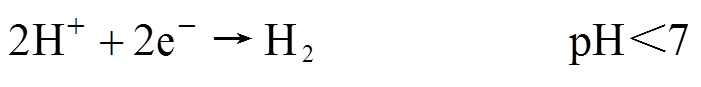
The most influencing variable that is a direct cause of stray current is the rail-to-earth conductance ( ), show inFig.2. Here, Us, IL, Is, In, Rn, Rp, Rin1 and Rin2 are defined as the traction substation voltage, train operating current, stray current, return current through rails, resistance of negative return circuit, resistance of positive circuit, rail-to-earth resistance at source end and rail-to-earth resistance at load end respectively.
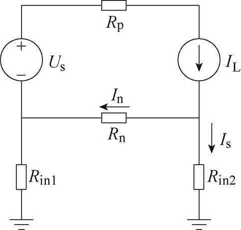
Fig.2 Basic stray current model
 (1)
(1) (2)
(2)
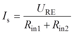
Equ.(2) indicates that the stray current is related to average rail potential (URE) and rail-to-earth conductance (). Therefore, low value of rail potential and good insulation of the running rails with respect to earth can limit stray currents considerably.
The standard provides a limiting value for stray current to ensure track life for 25 years (not for other civil structures), leading to two limits for open formation (e.g. ballasted or slab track, as for railways and metros) and closed formation (with top of rail leveled to the surrounding surface, such as asphalt, as for tram lines).
(1) ≤0.5S/km per rail and URE≤+5V for open formation.
(2) ≤2.5S/km per rail and URE≤+1V for closed formation.
For a double rail line the overall conductance limit must be multiplied by two. Furthermore, this value will change based on the average rail potential, such as calculated by electromechanical simulation, as a consequence of Equ.(2). The conductance limit remains effective during the entire system’s life cycle and must be met even after many years of operation, considering ageing of material, dust and other influences. Therefore, the initial limit value must be selected with sufficient margin and this is a point exposed to some discretion of the infrastructure owner: usual contractual values are in the range of 50 to 200W·km, corresponding to 0.005S/km to 0.04S/km[12-13].
Besides conductance, the other relevant quantity subject to limit is the average potential shift between the structure and earth in the hour of highest traffic, not to exceed +200mV for steel in concrete stru- ctures[14]. This is illustrated in Fig.3.
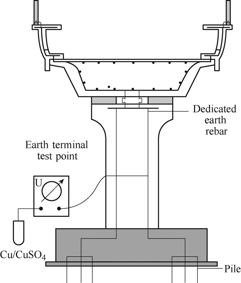
Fig.3 Average potential shift of structure
A similar criterion may be applied to the longitudinal voltage drop between any two points of the through-connected metal reinforced structure, such as viaducts or tunnels. Although a slightly different case from the potential shift previously considered, it is generally agreed the limit to be 200mV[11] in Fig.4.
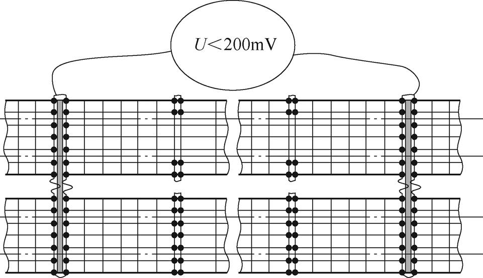
Fig.4 Longitudinal voltage drop of structure along line section
The mitigation measures can be arranged in four broad categories described in the following.
Three specific measures are used to decrease the resistance of the rail-return circuit.
3.1.1 Increase rail size or cross-sectional area
Stray current leakage is a result of the resistance relationship between the rail-to-earth return path and the running rail return path. A high resistance of the running rail negative return increases the voltage drop along the rails and, therefore, makes the rail-to-earth return circuit a more favorable path for the return current, thus causing stray current leakage.
The size of the rail is internationally standardized and increasing the cross-sectional area for reducing stray currents is not an available option. Similarly, structural and dynamical exigencies dictate the sele- ction of rail hardness and other mechanical properties, within the same cross section, affecting significantly the DC resistance values[15]. The rail resistance is to be measured in accordance to annex A.1 of EN 50122-2.
3.1.2 Improve track and rail cross bonding
The second important measure to decrease the running rail resistance is to maintain a continuous electrical path for the negative current return. This is accomplished by using continuously welded rails, or by using welded cable bonds between discontinuous sections of the track. The objective must be to ensure that the longitudinal rail resistance is not increased by more than 5% by the rail joints[11].
To achieve as low voltage drop as possible, running rails are welded, and rail-to-rail (RR) and track-to-track (TT) low-resistance bonds are provided at regular intervals. Typical interval for RR bonds is at every 150m (approx.) and for TT bonds is at every 300m (approx.). However, these distances are based on main factors such as headway, distance between traction substations, traction load, and others. Bonding must be compatible with the track circuit technology, if in use: metros are shifting consistently to CBTC (communication-based train control system) and other modern signaling systems based on balises and axle counters, tram lines have specific signaling technology, but railways still employ track circuits as an old reliable method including broken rail detection feature.
In some cases, it is not possible to reduce rail potential using cross bonds due to high headway and large distance between traction substations. In this scenario, it is suggested to install a return cable bonded to track at regular intervals. The size of the return cable is governed by the limit of rail potential prescribed by section 9.2 of EN 50122-1[16], dis- cussed in a wider perspective in Ref.[12].
3.1.3 Reduce distance between traction substations
Short distance between two substations decreases the length of positive feeder and the negative return circuit, and thereby reducing the voltage drop and making stray current paths less favorable. Traction substations typically will coincide with a passenger station, which provides added benefit in reducing stray current, since the current requirements of the trains are highest during acceleration, but the running rails return circuit voltage drops are the smallest due to the short length of track.
Specific measures used to increase the leakage path resistance are discussed below.
3.2.1 Maintaining an ungrounded negative return circuit
First and foremost, to increase the resistance of leakage paths to earth an ungrounded traction power system must be used.
Let us consider the case of insulated track, having a small uniform electrical conductance with the earth. In the case of a traction substation at one end and a train at the other, the major portion of traction current will flow through the running rails, and part will leak into the earth where rail potential is positive and will return to the rails where rail potential is negative. At equilibrium, the current entering will be equal to the current leaving and somewhere near the mid-point between train and traction substation the potential will be zero (“Pseudo earth”, see Fig.5a)[17].
In case, the negative busbar is earthed at the traction sub-station end, while maintaining the remaining track floating. It is observed the running rail potential will increase to double the value as the curve will shift to the origin, where the traction substation is connected to earth, as shown in Fig.5b. This will lead to more current leakage; thus, it is advisable to keep the system ungrounded[18-20].
However, to avoid impermissible touch voltage, voltage limiting devices shall be installed. Typically, they are installed at passenger stations where the probability of passenger entering the tracks is higher, including the contact with Platform Screen Doors[12].

Fig.5 Diagram of rail potential profile
3.2.2 Increasing the rail-to-earth resistance
This is the most influencing variable for stray current leaving the tracks. Rail fastener insulation is important, so that, high rail-to-earth resistance is maintained. In theory, stray currents from an ungrounded system should be low, as long as rail is not earthed along the line. By increasing this resistance, the stray current path is less favorable than the running rail return path, resulting in less stray current. Track design shall utilize insulated track fasteners on concrete track plinths or track slabs.
3.2.3 Isolating the yard track
Tracks in depots and workshops are concentrated in a small area and no major voltage drop arises. However, one needs to deal with the most restrictive touch voltage limits (50/60V[11]) and the general attitude of pursuing such limits by extensive earthing of tracks.
Sectioning and isolation of depot tracks results in smaller track sections for which selective earthing may be implemented (e.g. at workshops only), while increasing rail-to-earth resistance in other areas (that is beneficial for impact on infrastructure, such as building foundations, buried cables and reservoirs). Electrical isolation of depot track from the mainline track prevents the higher running rail voltages from being imposed on the depot track which are normally at lower voltages. The rectifier negative bus should be solidly bonded to the earth, to eliminate the hazard of high voltage developed between rails and earth. Fig.6 explains the typical arrangement of depot earthing.

Fig.6 Depot earthing arrangement
Stray current collection system (SCCS) is aimed at catching as much stray current as possible to limit their propagation to the surrounding environment[21-22]. All reinforced track sections shall meet the corrosion criteria of 200mV maximum as per EN 50122-2 and EN 50162. This criterion is intended for the voltage taken between any two points of the track or structure reinforcement.
There are two types of SCCS schemes, which have been adopted in various metro projects.
3.3.1 Floating stray current collection system
In this case, the track slab reinforcement is separated from the one of the substructures. Insulation layers shall thus be added to shear connectors bonding both structures as per Fig.7 and Fig.8[23]. This system ensures that the most stray current remains within the track slab. However, drawback of this arrangement is that in case one out of thousand shear connectors fails, that area will become hot spot and lead to corrosion over a longer period. Furthermore, it can affect the utilities running along the alignment.
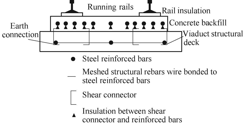
Fig.7 Floating SCCS
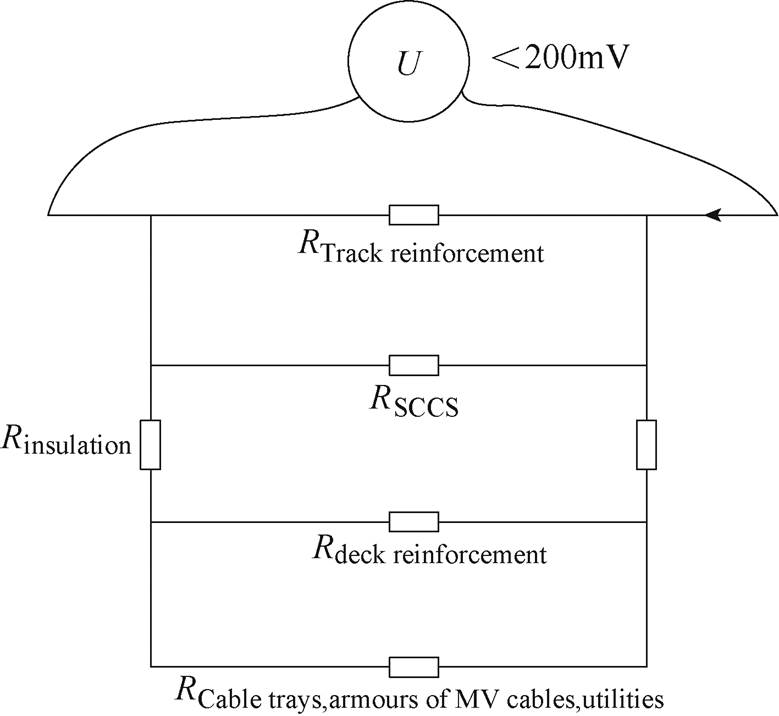
Fig.8 Floating SCCS electric model
In addition to the above insulation requirement, the reinforcement steel shall be longitudinally interconnected, so to form a mat that complies to the aforementioned corrosion criteria. Adequate measures must be deployed to ensure that bonds between adjacent plinths avoid being corroded by the atmospheric environment. This can be achieved by insulated cables, stainless or coated bare metal.
If the reinforcement is discontinuous due to structural or construction reasons (expansion joints, turnouts if the slab reinforcement cannot be used), this discontinuity shall be bridged by at least two cable bonds (minimum 50mm2 Cu each as a conductor in direct contact with rails) per track.
SCCS of each running rail shall be laid within the trackwork and completely segregated from the running rails. They shall be also cross bonded every approximated 100m. The following Fig.9 illustrates on how to achieve such cross-bonds.
At each above-mentioned interconnection between track slabs, the SCCS is made discontinuous, but bonded to a stray current collector cable (usually an insulated 70 mm2 or larger) through disconnectable links. Such facilities allow possible isolation of local SCCS for stray current monitoring purposes. Fig.10illustrates the electrical arrangement.

Fig.9 SCCS cross-bonding principles
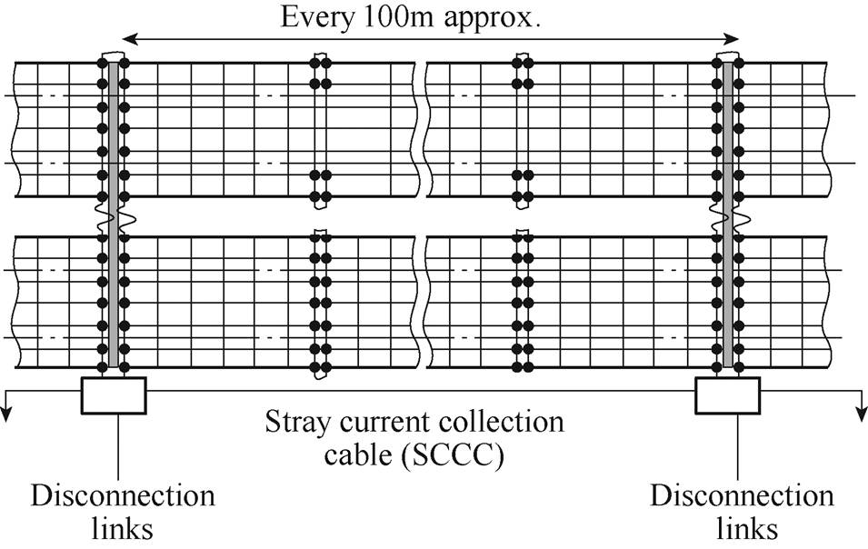
Fig.10 Floating SCCS interconnection
A stray current cubicle is located in traction substation (TSS) to connect the reinforcement to the traction system negative bus through a diode and switch system. The so-called drainage function is aimed to collect stray current that flows along the SCCS when the latter is under corrosion risk. To achieve this drainage function, a dedicated manual switch must be closed: this operation should be taken as the last resort only, since it brings the potential of the traction return circuit to earth (in turn increasing the overall amount of stray current). The drainage function is illustrated in Fig.11.
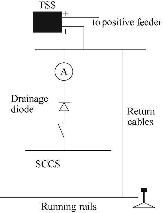
Fig.11 Drainage diode connection
Stray current is not easy to measure accurately[13]. Indeed, it can temporarily leave the rail and came back to it without any control on its path and values. However, it remains possible to measure the part flowing along the SCCS up to the TSS by closing the switch of the stray current cubicle, transforming the system from isolated to diode drained.
It is important to highlight that in case of floating SCCS, the structure earth cable (SEC), or parallel earth conductor (PEC), is separated from the stray current collector cable (SCCC). Fig.12 explains the typical cross-section of the viaduct with floating SCCS.
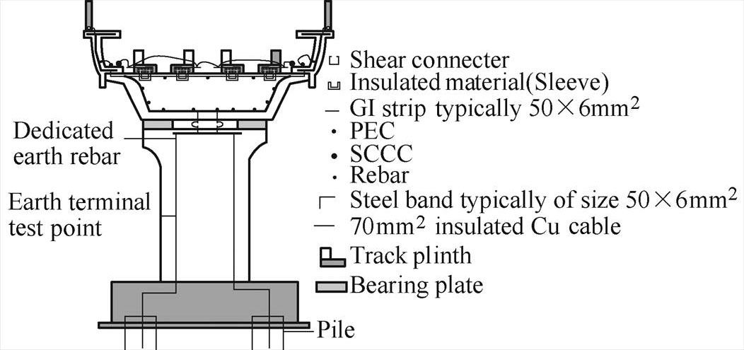
Fig.12 Floating SCCS typical cross-section
3.3.2 Earthed stray current collection system
In this case, the track slab reinforcement is bonded to the substructure one, as shown in Fig.13 and Fig.14. The shear connectors are either wire lashed or welded (preferable). Although this provides a lower resistance path for a potentially larger stray current to flow, the design is such that the maximum longitudinal voltage drop between any two points is kept well below 200mV.
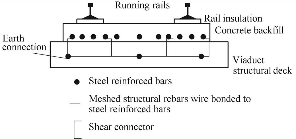
Fig.13 Earthed SCCS
While performing design calculations, it is preferable as a margin to take into consideration only the track slab rebars and SEC, or PEC. The SCCS is bonded then to both PECs and hence the earthing systems of passenger stations and depot buildings.

Fig.14 Earthed SCCS electric model
Where the reinforcement is made discontinuous for structural or construction reasons, this dis- continuity shall be bridged by at least two cable bonds (usually using 50mm2 for homogeneity of requirement when connecting to rails[16] and in general satisfying at once also lightning protection constraints). Mats of different tracks are cross bonded every approx. 100m. They shall be laid within the trackwork and com- pletely segregated from the running rails. To further reduce the longitudinal resistance of the reinfor- cement, the interconnected track slab reinforcement shall be bonded to the SECs/PECs every 100m as shown in Fig.15.
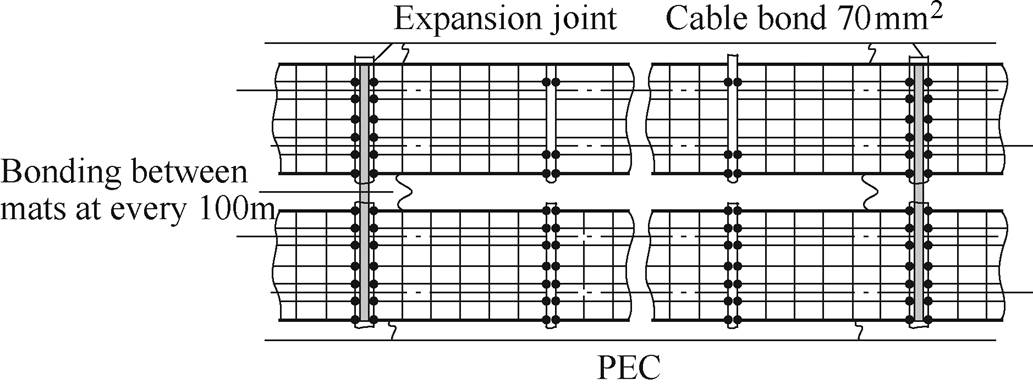
Fig.15 Earthed SCCS interconnection
It is important to note that in case of earthed SCCS, there is no separate SCCC. Fig.16shows the typical cross-section of a viaduct with earthed SCCS.
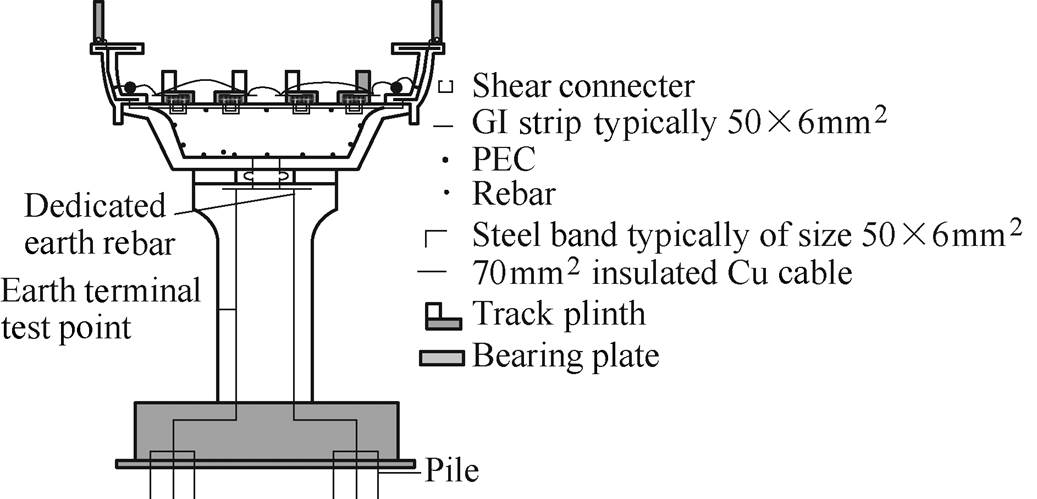
Fig.16 Earthed SCCS typical cross-section
3.3.3 Sizing of stray current collection system
To estimate the necessary size of the stray current collection system, criterion 3 defined in sec. 3.3 is addressed. However, before starting solving the related equations, as one of the most influencing input parameters, the rail-to-earth conductance must be assigned. This can be done once the criterion 1 in sec. 2.1 has been addressed and fulfilled. Therefore, it is recommended to first solve equations that provide the rail potential and stray current at the origin (leaving the rail), providing an indication of the maximum acceptable . Once the stray current criterion of 2.5A/km for a single track is satisfied, then the equations related to the longitudinal structure potential may be solved.
In order to estimate the worst-case scenario, it’s assume that the stray current flow through track rebars and PEC/SCCS only. This approach is adopted to design both floating SCCS (see Fig.8) and earthed SCCS (see Fig.14). In this case considering the advantage of less resistance offered by deck reinforcements, cable trays, handrails and other metallic object running in parallel to the track reinforcement. A lower resistance path would in fact decrease the longitudinal voltage drop and help achieving the limit set by EN 50122-2[11].
Typically, the worst case for highest average value of traction current will be in the section where the two traction substations are located farthest. To estimate the amount of stray current leakage, let us take a reference system with section length of 1km, train current 500A and rail-to-earth conductance for single track equal to 0.05S/km.
 (3)
(3)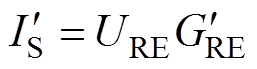 (4)
(4)
 (5)
(5)
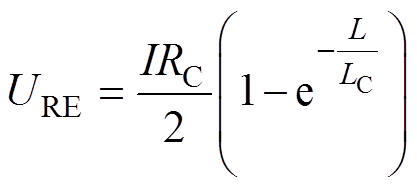
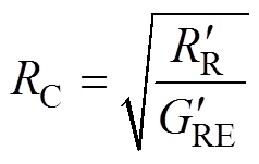
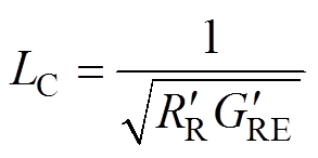 (6)
(6)where URE is the rail potential; I is the reference traction return current, taken as the average value in the considered section in the hour of highest load; RC is the characteristic resistance of the system running rails/structure; LC is the characteristic length of the system running rails/structure; L is the length of the considered line section;  is the longitudinal resistance of the running rails including parallel return conductors per length;
  is the conductance of the running rails vs. earth per length;
  is the stray current leaking from the rails relative to the length.
The results are URE=4.9V and =0.24A/km considering as 0.02W/km (with a conservative longitudinal resistance for heavy UIC 60 rails of 40mW/km including e.g. welding points[15]). It is evident that there is room for 1 000A of traction current in this example before the leakage limit of 0.5A/km is reached.
To evaluate the longitudinal voltage drop for the section length to be within 200mV, let us assume the same value of current (1 000A), section length (1km) and rail-to-earth conductance (0.05S/km) as above. There are two possibilities for selecting rebars arrangement. In the first case (1), taking all the rebars that form the part of structure design of track slab as depicted in Fig.17. In this case at least one stirrup must be welded or wire lashed (ideally required for a length 20 times the rebar diameter) to connect to the external PEC.
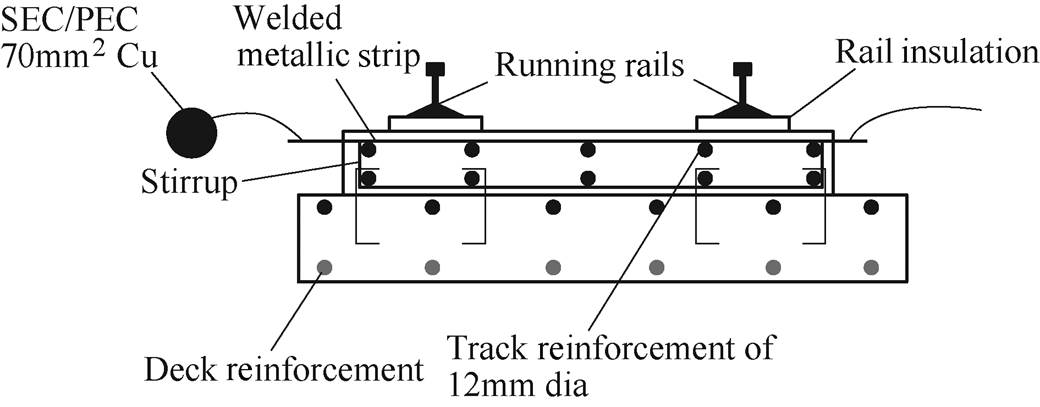
Fig.17 Case (1) cross-section
In the other case (2), considering the dedicated stray current collection rebars for calculations, as reported in Fig.18, assuming the other reinforcement rebars sufficiently insulated.
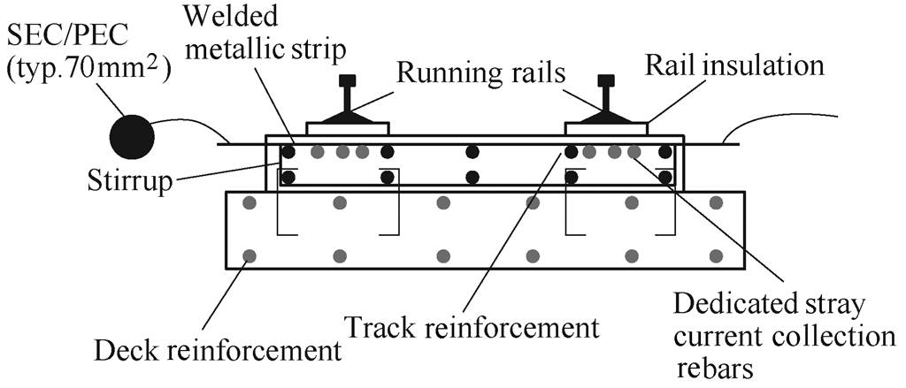
Fig.18 Case (2) cross-section
Using the formula defined in annex C.2 of EN 50122-2.
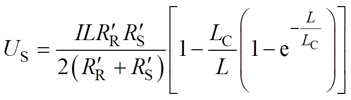 (7)
(7)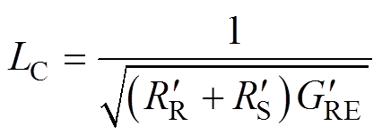 (8)
(8)
where US is the longitudinal voltage in the metal reinforced structure, is the resistance of the structure per length.
The results for different scenarios are shown below in Tab.1 and Tab.2.
Tab.1 Us potential for cases (1) and (2), described in Fig.17 and Fig.18
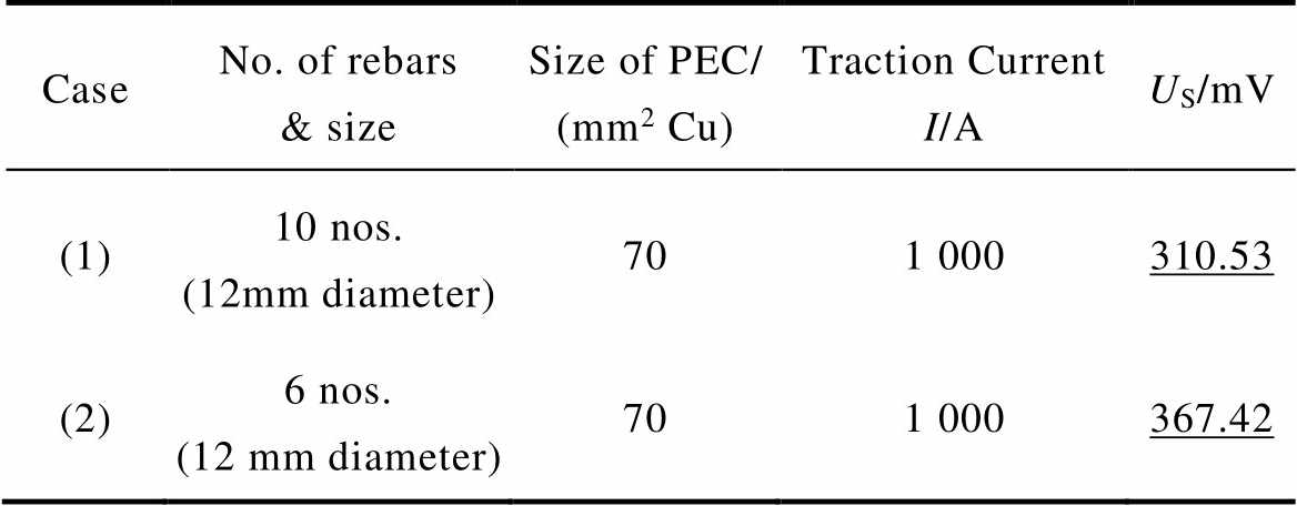
CaseNo. of rebars & sizeSize of PEC/ (mm2 Cu)Traction Current I/AUS/mV (1)10 nos. (12mm diameter)701 000310.53 (2)6 nos. (12 mm diameter)701 000367.42
Tab.2. Us potential for improvements to case (1)
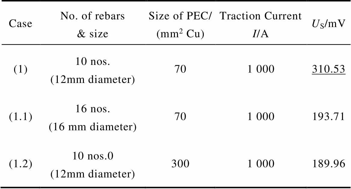
CaseNo. of rebars & sizeSize of PEC/ (mm2 Cu)Traction Current I/AUS/mV (1)10 nos. (12mm diameter)701 000310.53 (1.1)16 nos. (16 mm diameter)701 000193.71 (1.2)10 nos.0 (12mm diameter)3001 000189.96
While using the structure reinforcement of track as stray current collection rebars meets the requirement, whereas, in case providing dedicated stray current collection rebars, four rebars of 12mm diameter are needed along with structure reinfor- cement. As it is not possible to isolate dedicated stray current collection rebars structure reinforcement, thus, they can be avoided in case satisfing the criteria of 200mV.
The other scenarios with high traction current and no dedicated stray current rebars are provided. In this case either adding rebars to meet the requirement or changing their cross-sectional area or both. The other possibility is to increase the PEC size, as shown in the Tab.2.
Considering that running rails are not totally isolated from earth, stray current will leak into the earth when the running rails are the return path of traction current to the TSS negative bus. Therefore, by replacing the running rails return path with a specific current-returning rail/cable may solve stray current issue fundamentally[24]. Here, the current-returning rail/cable usually requires low longitudinal resistance for reducing rail potential, and a high rail-to-earth resistance to prevent stray current leakage.
The current-returning rail/cable scheme includes typical implementation methods: fourth rail and power electronic solutions. The former requires modification of the train to introduce the traction current directly into the added rail instead of running rails. While the latter may transfer the traction current to added cable with power electronic equipment without modifying the train.
Three typical current-returning rail/cable measures are introduced below.
3.4.1 Fourth rail system
Fig.19 shows the illustration of fourth rail system. Compared with the third rail configuration, a fourth rail is added to transfer traction current to sub- station[25]. The fourth rail can be mounted on high-insulation concrete sleepers to minimize the stray current leakage, but this is not possible for running rails which have to be seated on sleepers to carry the weight of trains. Therefore, without traction current on running rails and high insulation of fourth rail, the stray current issue of DC traction system may be solved fundamentally. But the fourth rail system requires the train modification and high cost; it’s only applied in a few lines, such as London Underground, Milan Metro Line 1, etc.
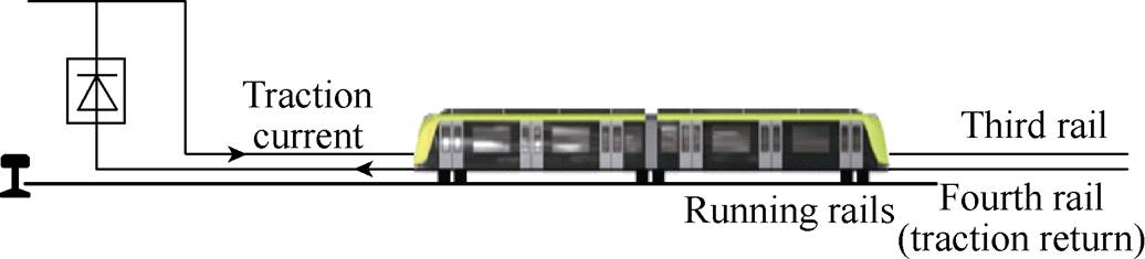
Fig.19 Fourth rail system
3.4.2 DC booster circuit traction power system
The configuration of DC booster circuit traction power system is shown as Fig. 20. Compared with the third rail configuration, DC booster system adds multiple DC boosters and specific return cable[26-27]. Here, DC boosters transfer the traction current to the return cable, and then reduce the stray current and rail potential. However, each DC booster circuit in Ref.[26] consists of two DC inductor and eleven switches, which leads to high cost, large volume and complex control. Thus, the added DC boosters may be not applicable in narrow space, such as tunnel. Meanwhile, unlike the booster transformer in AC railways, DC booster has a certain window period due to the dead time of switches, and the traction current flows back to substation through running rails during the window period. Therefore, such limitations make DC booster traction system to be difficult implement and limited effect.
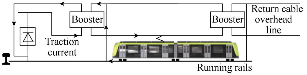
Fig.20 DC booster circuit traction power system
3.4.3 Negative resistance converter traction power system
Fig.21 shows the typical configuration of negative resistance converter (NRC) traction power system[28-30]. Similarly, NRC traction power system adds NRCs and multiple switch units (SUs) compared with the third rail configuration. Here, NRC has fewer components (i.e. one DC inductor and four switches) compared with DC booster. Thus, NRC is recom- mended to be installed in traction substation, and SUs with small volume may be installed directly in tunnels. SUs operate according to the position of train, and NRC provides negative voltage to make up for voltage drop caused by current-returning feeder cable. Then the rail current only exists on the train-running section, and the rail currents of no-train sections are zero. Therefore, NRC system achieves the stray current and rail potential mitigation effectively. However, NRC system requires accurate position detection to ensure the correct operation of SUs, and it lacks of direct test on the running railway lines because of immature technology, then NRC system still needs the further research to ensure the safe operation.
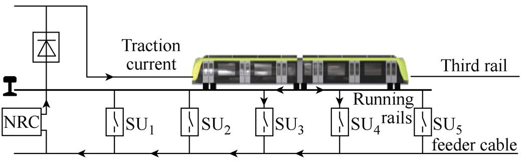
Fig.21 NRC traction power system
Based on the above stray current mitigation solutions, the performance comparison is shown as Tab.3. Here, the more stars (from 1 to 5), the higher effectiveness, cost, applicability and maturity, and the easier aging. Clearly, the traditional mitigation solutions generally have the high maturity, while the effectiveness is low and the aging is serious. And these solutions are mainly adopted during the construction of urban rail transit.
Correspondingly, the maturity of the special current-return rail/cable is not high enough, but it has high and permanent effectiveness compared with the traditional solutions. And the special current-return rail/cable can be adopted both for the existing system and new lines during the construction, which leads to the high applicability in urban rail transit. Further- more, NRC traction power system also shows better application prospect in urban rail transit stray current mitigation for the higher effectiveness and low cost.
Tab.3 Performance comprison of stray current mitigation solutions
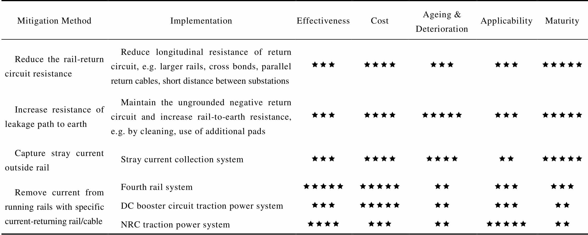
Mitigation MethodImplementationEffectivenessCostAgeing & DeteriorationApplicabilityMaturity Reduce the rail-return circuit resistanceReduce longitudinal resistance of return circuit, e.g. larger rails, cross bonds, parallel return cables, short distance between substationsêêêêêêêêêêêêêêêêêê Increase resistance of leakage path to earthMaintain the ungrounded negative return circuit and increase rail-to-earth resistance, e.g. by cleaning, use of additional padsêêêêêêêêêêêêêêêêêêêê Capture stray current outside railStray current collection systemêêêêêêêêêêêêêêêêêê Remove current from running rails with specificcurrent-returning rail/cableFourth rail systemêêêêêêêêêêêêêêêêêê DC booster circuit traction power systemêêêêêêêêêêêêêêê NRC traction power systemêêêêêêêêêêêêêêêê
Aiming at the stray current in urban rail transit, this paper studies the principle of stray current and its corrosion based on a simplified stray current model, and discusses the design criteria for stray current mitigation. Moreover, the stray current mitigation solutions are analyzed and discussed in detail. The results show that:
1) The traditional stray current mitigation solutions should be implemented in strict accordance with the standards during the construction phase.
2) If the traditional solutions are no longer suitable for the existing system, the stray current in the system can be further suppressed by adopting specific current-returning rail/cable.
3) In such current-returning rail/cable scheme the traction current is transferred from the rail to the added rail/cable, which may solve the stray current issue fundamentally.
4) NRC traction power system shows a good application prospect in existing system stray current mitigation with the advantages of high effectiveness and low cost.
Reference
[1] Saud A M, Paul F. Stray current corrosion and mitigation: a synopsis of the technical methods used in DC transit systems[J]. IEEE Electrification Magazine, 2014, 2(3): 22-31.
[2] Yang Xiaofeng, Xue Hao, Trillion Q Z. Stray current and rail potential dynamic simulation system based on bidirectional variable resistance module[J]. Transa- ctions of China Electrotechnical Society, 2019, 34(13): 2793-2805.
[3] Alberto D, Federica F, Sonia L. Stray current effects mitigation in subway tunnels[J]. IEEE Transactions on Power Delivery, 2012, 27(4): 2304-2311.
[4] Chen Zhipei, Dessi K, Klaas V B. A review on stray current-induced steel corrosion in infrastructure[J]. Corrosion Reviews, 2017, 35(6): 397-423.
[5] Katarina V, Stjepan L, Marijana S. Corrosion and stray currents at urban track infrastructure[J]. Gradevinar (Journal of the Croatian Association of Civil Engineers). 2020, 72(7): 593-606.
[6] Charalambos A C, Ian C, Pete A, et al. A holistic stray current assessment of bored tunnel sections of DC transit systems[J]. IEEE Transactions on Power Delivery, 2013, 28(2): 1048-1056.
[7] Liu Sheng, Zhou Qi, Lin Xiaohong, et al. Infinitesimal method based calculation of metro stray current in multiple power supply sections[J]. IEEE Access, 2020, 8: 96581-96591.
[8] Zakir A. Principles of corrosion engineering and corrosion control[M]. Oxford: Butterworth-Heinemann, 2006.
[9] Du Guifu, Zhang Dongliang, Wang Chonglin, et al. Effect of traction current transmission among power sections on rail potential in DC mass transit system[J]. Transactions of China Electrotechnical Society, 2016, 31(11): 129-139.
[10] Ian C, Charalambos A C, Pete A, et al. Stray current control in DC mass transit systems[J]. IEEE Transactions on Vehicular Technology, 2005, 54(2): 722-730.
[11] EN 50122-2. Railway applications-fixed installations- electrical safety, earthing and the return circuit-part 2: provisions against the effects of stray currents caused by d.c. traction systems[S]. Brussels, 2010.
[12] Andrea M. Electrical safety and stray current protection with platform screen doors in DC rapid transit[J]. IEEE Transactions on Transportation Electrification, 2021, 7(3): 1724-1732.
[13] Andrea M. Stray current protection and monitoring systems: characteristic quantities, assessment of performance and verification[J]. Sensors, 2020, 20(22): 6610.
[14] EN 50162. Protection against corrosion by stray current from direct current systems[S]. Brussels, 2004.
[15] Andrea M. Impact of rail impedance intrinsic variability on railway system operation, EMC and safety[J]. International Journal of Electrical and Computer Engineering (IJECE), 2021, 11(1): 17-26.
[16] EN 50122-1. Railway applications-fixed installations- electrical safety, earthing and the return circuit-part 1: protective provisions against electric shock[S]. Brussels, 2011.
[17] Lowes F J. DC railways and the magnetic fields they produce-the geomagnetic context[J]. Earth, Planets and Space, 2009, 61: 1-15.
[18] Dev P. DC stray current in rail transit systems and cathodic protection[J]. IEEE Industry Applications Magazine, 2016, 22(1): 818-824.
[19] Chien H L, Chien J L. Assessment of grounding schemes on rail potential and stray currents in a DC transit system[J]. IEEE Transactions on Power Delivery, 2006, 21(4): 1941-1947.
[20] Alamuti M M, Nouri H, Jamali S. Effects of earthing systems on stray current for corrosion and safety behaviour in practical metro systems[J]. IET Elec- trical Systems in Transportation, 2011, 1(2): 69-79.
[21] Liu Wei, Li Tian, Jie Zheng, et al. Evaluation of the effect of stray current collection system in DC- electrified railway system[J]. IEEE Transactions on Vehicular Technology, 2021, 70(7): 6542-6553.
[22] Du Guifu, Wang Jun, Jiang Xingxing, et al. Evaluation of rail potential and stray current with dynamic traction networks in multitrain subway systems[J]. IEEE Transactions on Transportation Electrification, 2020, 6(2): 784-796.
[23] Jordi C, Jose S A, Joan R D. Modelled, simulation and design of collecting grid of stray currents in slab track in DC electrified railway systems[C]//IEEE International Conference on Electrical Systems for Aircraft, Railway, Ship Propulsion and Road Vehicles & International Transportation Electrification, Nottingham, UK, 2018: 1-7.
[24] Wang Miao, Yang Xiaofeng, Trillion Q Z, et al. DC autotransformer-based traction power supply for urban transit rail potential and stray current mitiga- tion[J]. IEEE Transactions on Transportation Elec- trification, 2020, 6(2): 762-773.
[25] Farah A A R, Mohd Z A A K, Miszaina O, et al. Review of the AC overhead wires, the DC third rail and the DC fourth rail transit lines: issues and challenges[J]. IEEE Access, 2020, 8: 213277-213295.
[26] Reza F, Siamak F, Seyed S F. A new novel DC booster circuit to reduce stray current and rail potential in DC railways[C]//Compatibility and Power Electronics, Badajoz, Spain, 2009: 457-462.
[27] Reza F, Siamak F. A new novel power electronic circuit to reduce stray current and rail potential in DC railway[C]//International Power Electronics and Motion Control Conference, Poznań, Poland, 2008: 1575-1580.
[28] Jingda G, Xiaofeng Y, Trillion Q Z, et al. Negative resistance converter traction power system for reducing rail potential and stray current in the urban rail transit[J]. IEEE Transactions on Transportation Electrification, 2021, 7(1): 225-239.
[29] Gu Zhan, Yang Xiaofeng, Jingda G, et al. Modeling of negative resistance converter traction power system[C]//IEEE Energy Conversion Congress and Exposition, Detroit, USA, 2020: 6367-6371.
[30] Gu Jingda, Yang Xiaofeng, Trillion Q Z, et al. Rail potential and stray current on negative resistance converter traction power system under different grounding schemes and train conditions[J]. Transactions of China Electrotechnical Society, 2021, 36(8): 1703-1717.
摘要 杂散电流会造成电气化交通系统附近金属结构腐蚀,该现象在普遍采用直流牵引供电的城市轨道交通中尤为突出。该文分别对城市轨道交通新建线路和运营阶段的现有线路的杂散电流治理和防护措施进行讨论。对设计阶段的新建线路而言,可采用包括优化牵引变电所位置、减小轨道纵向电阻、在道床中安装杂散电流收集系统等措施。对处于运营阶段的现有线路而言,除了采取在走行轨上并联线缆或走行轨间焊接均流线等以增大回流路径截面积措施外,通过电力电子的静止变换器(如负阻变换器等)控制回流路径杂散电流的方法也是极具潜力的治理措施;上述单元可以部署在特定点,以实现对轨道电位过高或出现初期腐蚀位置处的定点治理。
关键词:城市轨道交通 杂散电流 腐蚀 杂散电流收集 杂散电流缓解 负阻变换器
中图分类号: TM922
DOI: 10.19595/j.cnki.1000-6753.tces.210923
This work is supported by the Key Program of National Natural Science Foundation of China (51737001).
Received June 30, 2021;
Revised August 02, 2021.
Notes Brief
Sahil Bhagat male, born in 1991, Senior EMC Engineer at Hitachi Rail, Major research interests include grounding system design, DC stray currents, electromagnetic compatibility, and power system protection.E-mail: Sahil.Bhagat@hitachirail.com
Xiaofeng Yang male, born in 1980, IEEE Senior Member, PhD, Major research interests include safety power supply in rail transit, high power energy conversion, wide band gap devices application.E-mail: xfyang@bjtu.edu.cn (Corresponding author)
Andrea Mariscotti male born in 1968, IEEE Senior Member, PhD, Major research interests include electrical safety, stray current, electromagnetic compatibility and human exposure in electrified transports, measurement science and design of instrumentation.E-mail: andrea.mariscotti@unige.it (Corresponding author)
(编辑 陈 诚)