图1 拓扑结构
Fig.1 Topology diagram
摘要 常规分布式潮流控制器(DPFC)需通过3次谐波电流以实现串联侧与系统的有功功率交换,串联侧所在支路首末端分别需△/YN、YN/△联结型变压器,因此在配电网中的安装地点受到一定限制。为此该文提出一种适用于配电网的新DPFC(NDPFC)拓扑;分析NDPFC工作原理,应用配电网典型系统验证其潮流调节范围与调控特性;此外,研究NDPFC串并联侧电磁暂态数学模型,为提高鲁棒性与控制精度,提出一种采用三环控制的串联侧Ⅰ、Ⅱ控制策略;最后,在不同配电网场景下,通过仿真验证了NDPFC可实现配电网综合潮流调控、补偿三相不平衡、促进新能源消纳,有效地提高了配电网电能质量。
关键词:新分布式潮流控制器(NDPFC) 三环控制 综合潮流调控 三相不平衡 新能源消纳
随着我国电力需求的增加与国民经济日益发展,以风能、太阳能为代表的新能源装机规模快速增加。大量的二次设备投入、汽车充电桩逐渐普及、新能源电力自身的波动性与间歇性、含新能源电源的电力系统双侧随机性以及线路输送能力限制[1],将导致配电网可能存在线路潮流可控性低、三相不平衡、新能源消纳能力不足等问题[2-5]。同时,不受控的潮流会造成部分区域电力供给不足、线路传输损耗大等问题,甚至降低系统稳定性和可靠性[6]。
柔性交流输电技术(Flexible Alternating Current Transmission Systems, FACTS)可以优化潮流分布,提高电网电能质量。并联型FACTS装置可补偿无功功率、稳定母线电压、提高系统运行稳定性[7-9],文献[9]提出了不平衡条件下的星形联结的链式配电网静止同步补偿器(Distribution Static Synchronous Compensators, D-STATCOM)控制策略,可同时补偿无功功率与负序电流。串联型FACTS装置可改善线路电压、降低线路损耗、提高线路输送容量,应用于配电网可实现线路有功潮流调控、三相不对称补偿、谐波抑制等功能[10-13],文献[13]提出采用超级电容器储能的动态电压恢复器以有效提高配电网电能质量,但功率损耗较大、效率太低[14]。文献[15]提出一种多并联静止同步补偿器(Multiple Static Synchronous Series Compensator, MSSSC)以提高线路潮流调控灵活性,但无法实现综合潮流调控。分布式静止串联补偿器(Distributed Static Series Compensator, DSSC)可解决集中式装置成本高、灵活性与可靠性不足的问题,国内外针对DSSC的控制策略、选址定容、提升系统可靠性等方面进行了大量的研究[16-18]。
串并联混合型FACTS装置有统一潮流控制器(Unified Power Flow Controller, UPFC)、分布式潮流控制器(Distributed Power Flow Controller, DPFC),均可实现稳定电力系统母线电压、调节线路综合潮流、阻塞调度等功能[19-21]。文献[22]提出了一种基于多电平UPFC的三相不对称抑制策略,但UPFC高额的造价及较大的占地需求限制了其在配电网的应用。常规DPFC兼顾了UPFC的强大功能性和DSSC的高经济性、灵活性、可靠性等优点,文献[23-24]分别提出了常规DPFC多目标优化、非线性反馈控制策略,但均需向系统注入3次谐波电流以实现串联侧与系统的有功功率交换,这会引起额外的线路损耗,且安装支路两端需中性点接地的变压器以形成3次谐波回路,并不是所有配电网变压器类型及中性点接地方式都能满足常规DPFC的需求。
针对以上问题,本文拟提出一种适用于配电网的新型串并联混合型FACTS装置——新分布式潮流控制器(Novel Distributed Power Flow Controller, NDPFC)。首先对NDPFC拓扑结构和工作原理进行研究,再分析其潮流调节范围与潮流调控特性,得出NDPFC的电磁暂态数学模型,研究可充分发挥NDPFC性能的相关控制策略,并通过仿真验证所提NDPFC对现代配电网控制的适应性。
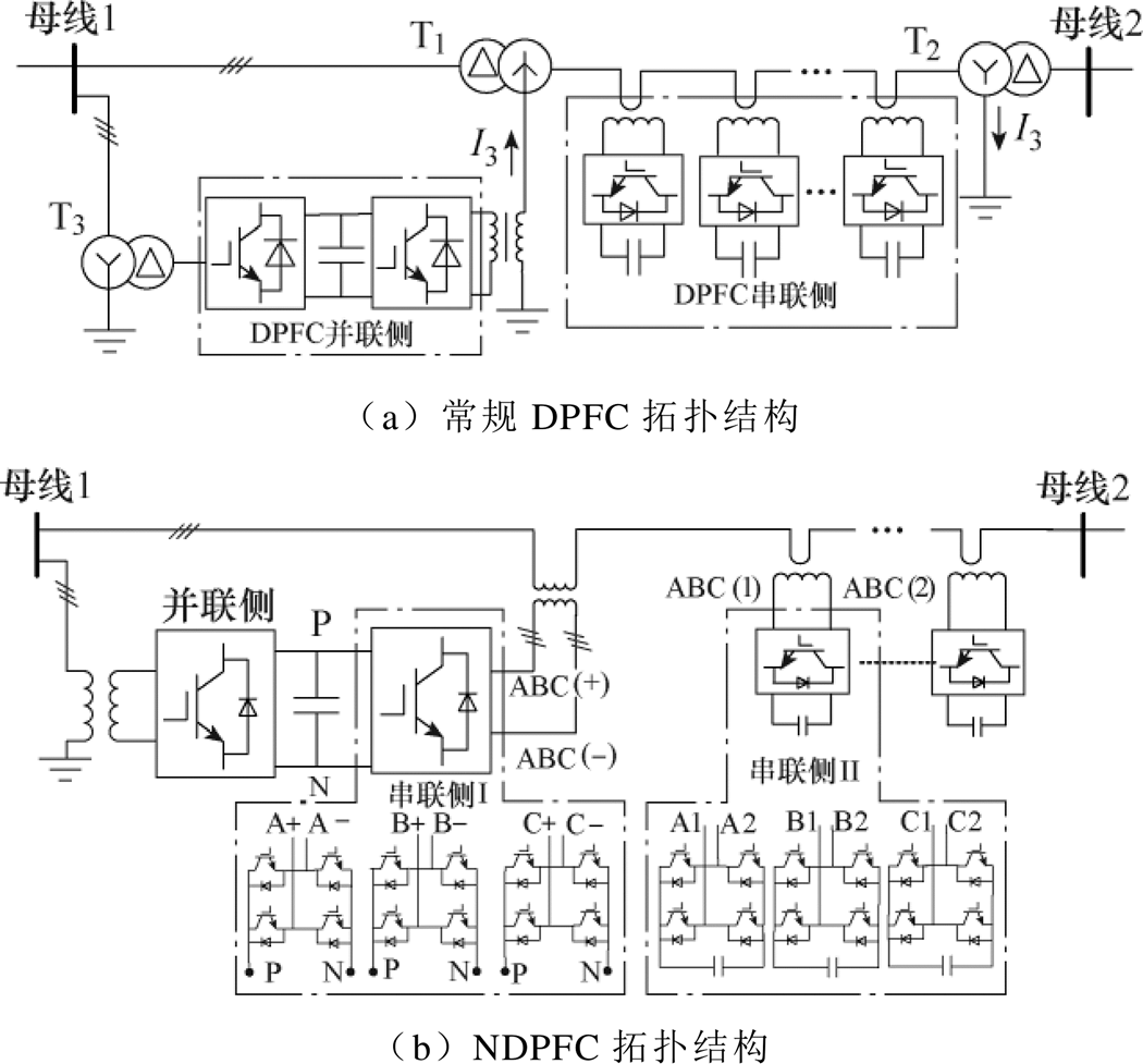
拓扑结构如图1所示。常规DPFC拓扑结构如图1a所示,需经△/YN联结的变压器T1中性点向系统注入3次谐波电流以实现串联侧与系统的有功功率交换[25],另需YN/△联结的变压器T2,以形成3次谐波回路。而中低压配电网变压器中性点一般采取不接地或经阻抗接地,且3次谐波电流会增加系统损耗。NDPFC拓扑结构如图1b所示,对变压器型号与接地方式无特殊要求,且无需通过3次谐波进行串并联能量交换,更适用于配电网。
图1 拓扑结构
Fig.1 Topology diagram
NDPFC并联侧由并联变压器、三相变流器、公共直流电容组成。串联侧分为串联侧Ⅰ与串联侧Ⅱ,其中,串联侧Ⅰ为三个共直流侧(并联侧公共直流电容)的单相变流器,经三相隔离变压器串入电力线路;串联侧Ⅱ包含多组(A、B、C三个单相为一组)单相变流器,通过单匝耦合变压器串入线路。
NDPFC并联侧功能与UPFC/DPFC一致,国内外已有大量的研究[22-26],本文不再赘述。电压补偿矢量如图2所示。DPFC、NDPFC串联侧电压补偿矢量分别如图2a、图2b所示。图中,Vs、Vr、d、q 分别为串联侧所在支路首、末端节点电压与对应相位,IL为线路电流,VXR为线路阻抗上的压降,Vse为常规DPFC串联侧等效补偿电压,Vsed为NDPFC串联侧Ⅰ等效补偿电压,Vseq为串联侧Ⅱ等效补偿电压。为实现DPFC的综合潮流调控功能,NDPFC串联侧应用dq解耦思想,串联侧Ⅰ提供与线路电流同相/反相的电压Vsed,串联侧Ⅱ提供与线路电流垂直的电压Vseq,通过调节Vsed、Vseq的大小与方向,等效补偿幅值相位均可变的电压Vse。
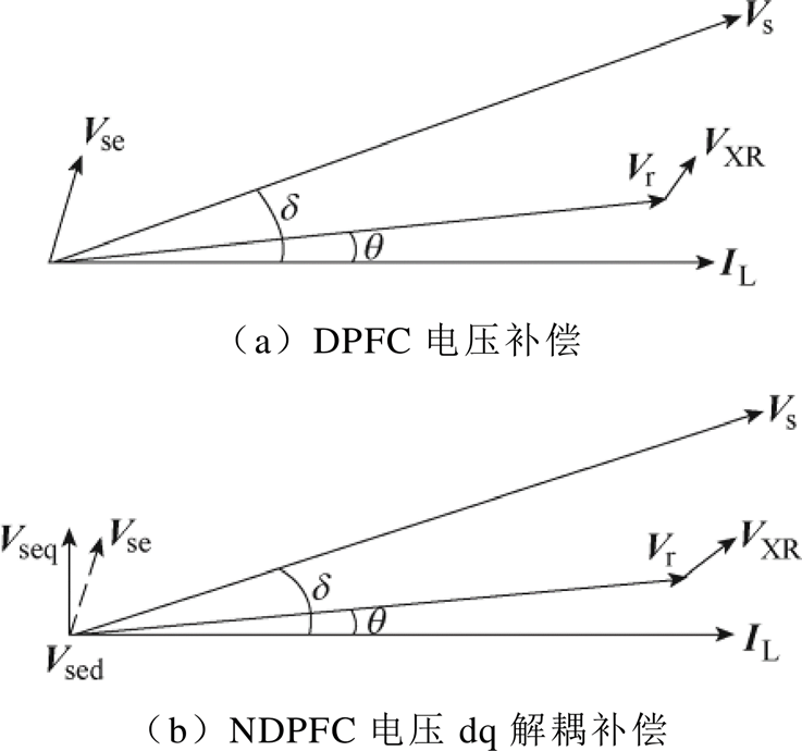
图2 电压补偿矢量
Fig.2 The phasor diagram of voltage compensation
当串联侧Ⅱ单独工作时,可工作于容性/感性状态,对应的补偿方式如图3所示。
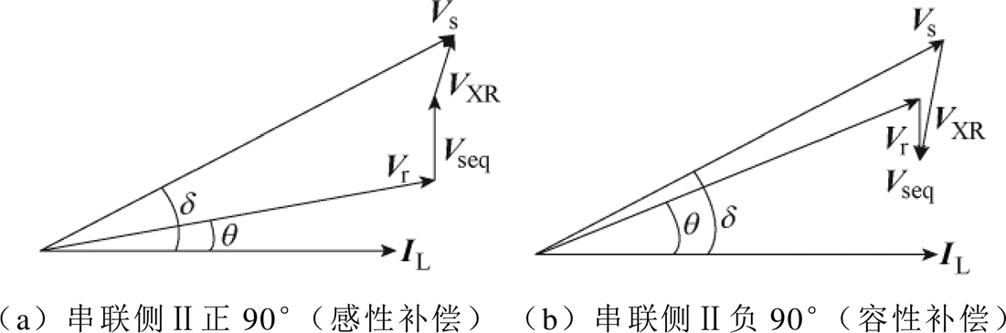
图3 串联侧Ⅱ补偿方式
Fig.3 Compensation for series side Ⅱ
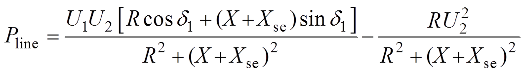
为分析潮流控制的原理,选用的电力线路简化电路如图4所示。图中,首末端电压分别为 ,相位差为
,相位差为 ,I为线路电流,R和jX分别为线路等效电阻与电抗。
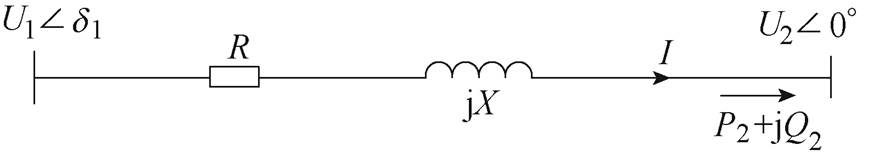
图4 电力线路简化电路
Fig.4 Simplified block diagramfor distribution line model
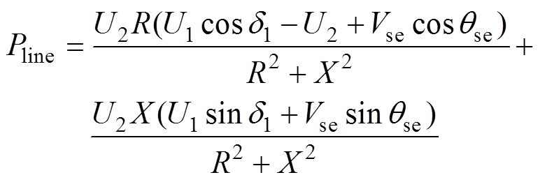
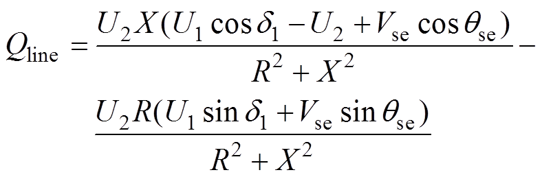
线路末端的有功潮流和无功潮流分别为
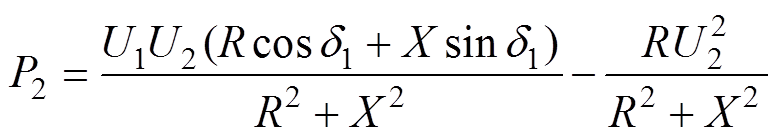 (1)
(1)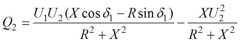 (2)
(2)
设补偿电压 对应等效输出阻抗为Xse,则
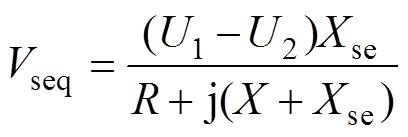 (3)
(3)此时对应线路末端有功潮流 、无功潮流
、无功潮流 分别为
分别为
 (4)
(4)
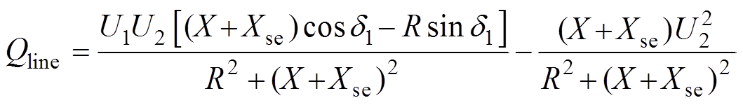 (5)
(5) 结合配电网特点:①配电网R X要远大于输电网,一般在12.5左右;②支路首末端电压相位差非常小;③配电网功率因数较高。令首端电压有效值为1.025(pu),初相位为3°,末端电压有效值为1.0(pu),初相位0°,线路阻抗
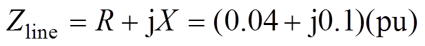 ,与第3节仿真参数一致。令
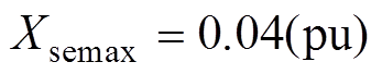 ,结合式(3)~式(5),补偿电压Vseq的潮流调节范围如图5所示。
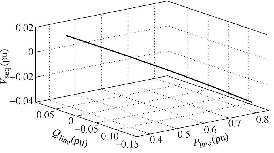
图5 Vseq潮流调节范围
Fig.5 The power flow regulation range diagram of Vseq
当串联侧Ⅰ、Ⅱ协同工作时,可逆变出幅值相位均可变的电压 ,支路末端潮流满足
 (6)
(6) (7)
(7)
系统参数与前述一致,取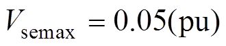 ,
, 为0~2p,NDPFC的潮流运行范围如图6所示。
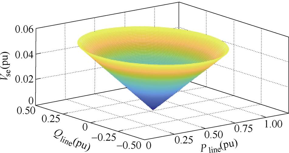
图6 NDPFC潮流运行范围
Fig.6 Power flow regulation diagram of the NDPFC
由图6可以看出,NDPFC串联侧Ⅰ、Ⅱ协同工作时,可以实现线路潮流的综合调控。Vseq、Vsed潮流调节特性如图7所示。
由图7可见,在典型配电网系统中,Vseq调节有功潮流能力优于Vsed,Vsed调节无功潮流能力优于Vseq。因此串联侧Ⅰ控制目标为线路无功潮流,串联侧Ⅱ控制目标为线路有功潮流。配电网功率因数较高,无功潮流调节范围较小,故串联侧Ⅰ所需容量很小;而串联侧Ⅱ调节有功潮流,调节范围较大,串联侧Ⅱ所需总容量也较大,与其分布式布置方式相匹配。
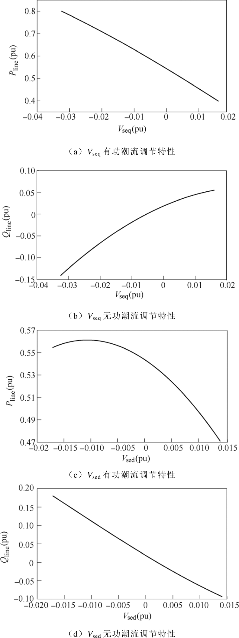
图7 Vseq、Vsed潮流调节特性
Fig.7 Vseq and Vsed power flow regulation characteristic chart
本节根据NDPFC拓扑结构推导出并、串联侧数学模型,为提高控制精度,提出并联侧双环控制策略与串联侧Ⅰ、Ⅱ的三环控制策略。
NDPFC并联侧等效电路模型如图8所示。
图8 并联侧等效电路模型
Fig.8 Equivalent circuit model for NDPFC of parallel side
图8中, 分别为并联侧接入点母线A、B、C相电压,
 分别为换流器A、B、C相输出电压,
 为输出滤波阻抗,

 为网侧流入换流器的电流,
 为并联侧公共直流电容电压。由图8可知
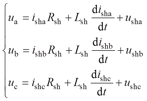 (8)
(8)将式(8)进行Park变换,可以得到同步旋转坐标系下NDPFC并联侧的数学模型为
 (9)
(9)
式中,下标d和q分别表示变量的d轴、q轴分量。并联侧输出电压的d轴分量与q轴分量分别为
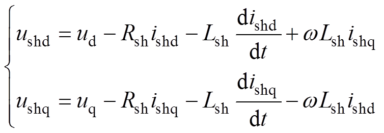 (10)
(10) NDPFC并联侧通过与系统交换无功功率以维持接入点母线电压 的稳定。为保证并联侧可靠运行,并为串联侧Ⅰ变流器提供稳定的直流电压,需维持公共直流电容电压的稳定。对应控制系统结构框图如图9所示。图中,下标ref表示变量的参考值或给定值;
 为并联侧接入点母线电压 幅值。
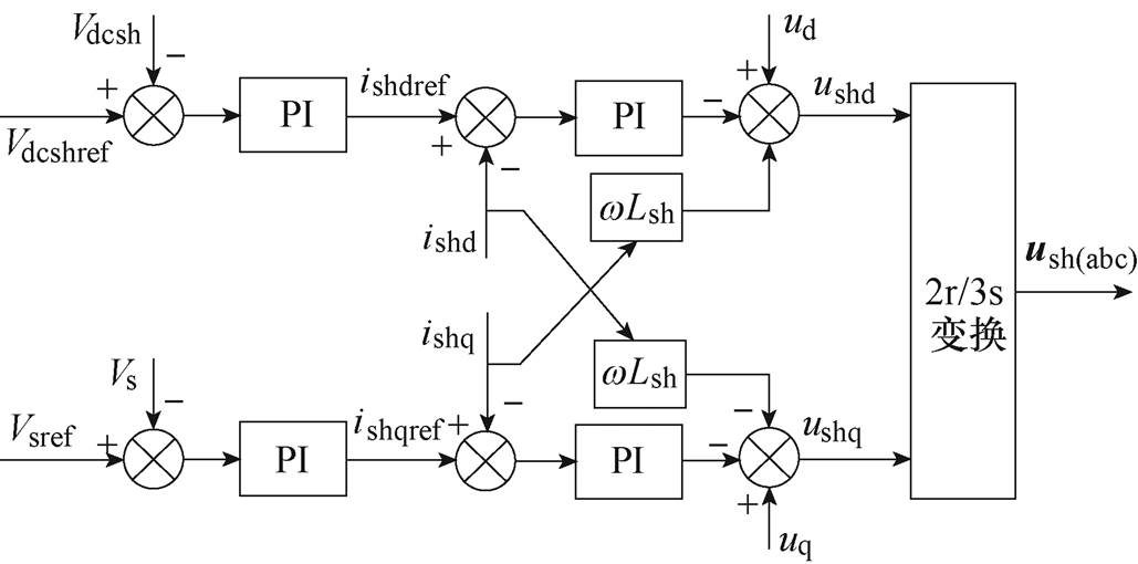
图9 NDPFC并联侧控制系统结构框图
Fig.9 The control system structure diagram of parallel side for NDPFC
NDPFC串联侧单相变流器等效模型如图10 所示。 为串联侧左侧接入点对地电压,
 为右侧接入点对地电压,Rse为串联侧等效内阻,Lse、
 分别为单相变流器滤波电感、电容,
 为网侧流入电流,
 为经LC滤波后流经变流器的电流,
 为串联侧逆变电压,
 为单相变流器电容电压。可得
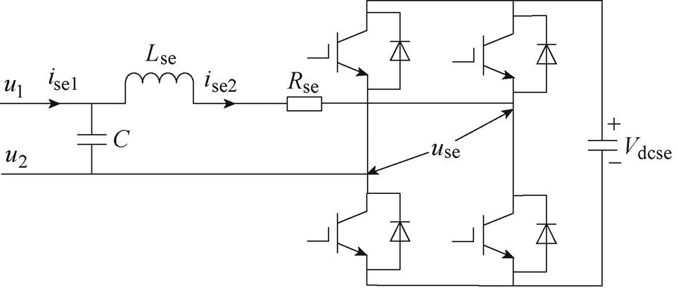
图10 NDPFC串联侧等效模型
Fig.10 Equivalent circuit model of series side for NDPFC
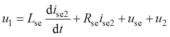 (11)
(11)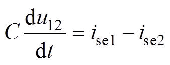 (12)
(12)
通过构造与原变量滞后p/2的变量以实现单相坐标变换。假设 为原变量,
为原变量, 为滞后p/2的量,
 为定向相位。则
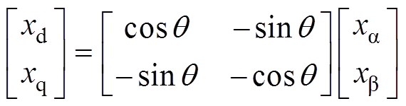 (13)
(13)结合式(11)~式(13),进行单相Park变换,串联侧单相变流器dq坐标系下数学模型为
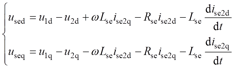 (14)
(14)
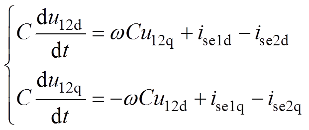 (15)
(15) 式中, 为串联侧两侧电压差;
 为系统频率。NDPFC串联侧Ⅱ需控制线路末端有功潮流以及自身电容电压Vdcse,其控制系统结构框图如图11所示。
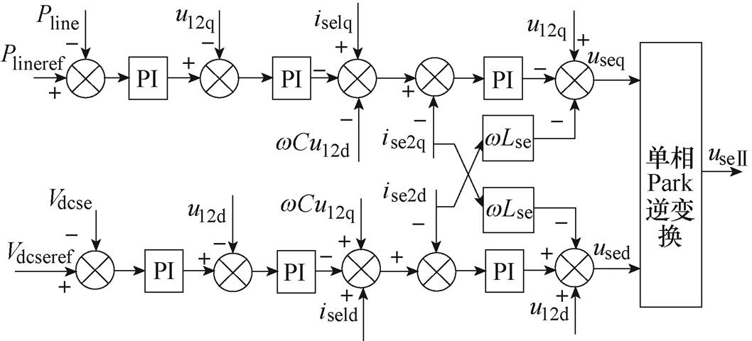
图11 串联侧Ⅱ控制系统结构框图
Fig.11 The diagram of control system structure for series side Ⅱ
 为串联侧Ⅱ等效输出电压。串联侧Ⅰ的电容电压由并联侧控制,因此
 直接给0。其控制系统结构框图如图12所示。
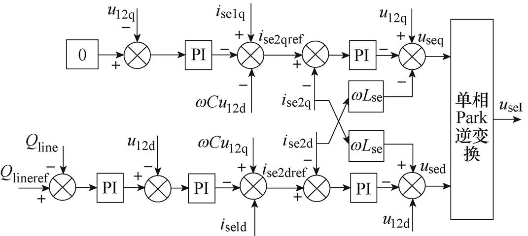
图12 串联侧Ⅰ控制系统结构框图
Fig.12 The diagram of control system structure for series sideⅠ
 为串联侧Ⅰ等效输出电压。综合图11、图12可以看出,通过串联侧Ⅰ、Ⅱ的协同控制,可同时调节目标线路有功、无功潮流,实现配电网综合潮流调控。
含NDPFC的仿真系统如图13所示。系统结构参数如下:首端电压u1有效值为10.25kV,初相位为3°;末端电压u2有效值为10kV,初相位为0°;线路阻抗Z1=0.0126+j0.0314W,Z2=Z4=0.789+j1.97W,Z3=0.942+j2.355W,NDPFC并联侧接于节点Ⅰ,串联侧Ⅰ通过三相隔离变压器串接于线路Ⅰ-Ⅱ上,而串联侧Ⅱ有两组(三个单相变流器为一组),均匀布置于Ⅰ-Ⅱ支路上。 为首端电源输出功率,
 为Ⅰ-Ⅱ支路末端功率,IL为Ⅰ-Ⅱ支路电流,
 为用户侧功率,新能源电源
 输出功率恒定为Px,Px=1.23MW;本地负荷
 =0.75MW。不对称模块用于模拟三相不对称应用场景,内为不对称阻抗,其中,A相为0.08+j0.197W,B相为0.151+ j0.377W,C相为0.01W。
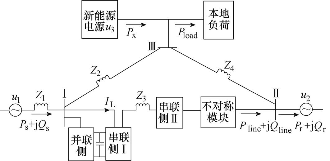
图13 含NDPFC的仿真系统
Fig.13 Simulation system with NDPFC
此实验中NDPFC串、并联均投入,新能源与负荷以及不对称模块不投入。
配电网综合潮流调控仿真结果如图14所示。Ⅰ- Ⅱ支路末端初始潮流为2.2+j0.039MV·A。1.5s时潮流指令给定值为2.4MW+j0Mvar。经0.15sⅠ-Ⅱ支路末端有功潮流达到2.4MW并保持稳定,无功潮流经0.5s达到0Mvar并保持稳定。
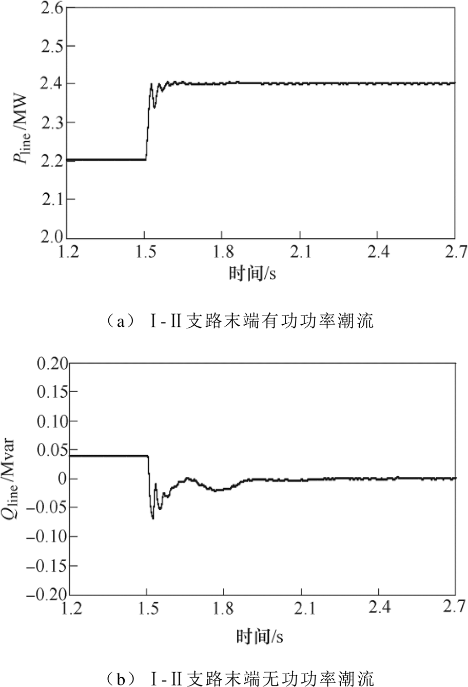
图14 配电网综合潮流调控仿真结果
Fig.14 Simulation results of comprehensive power flow control of distribution network
NDPFC可通过分相控制对配电网进行不对称补偿,以解决配电网不对称问题。
本实验通过投入三相不对称阻抗模块以模拟三相不平衡,其仿真结果如图15所示。未投入NDPFC前,NDPFC所在线路电流呈现不对称的现象,其中正序电流 =0.119kA,负序电流
 与零序电流
与零序电流 近似相等,约为0.005kA,不对称度为4.20%;1.5s时,NDPFC开始对线路进行不对称补偿,、迅速下降,经0.2s降为0,三相电流对称;NDPFC投入前A、B、C三相潮流分别为0.683+j0.019MV·A、0.635+ j0.018MV·A、0.736+j0.018MV·A,经过NDPFC的分相不对称补偿,A、B、C三相潮流最终达到一致,且等于不对称时三相潮流平均值,即0.685+ j0.0183MV·A。在进行不对称补偿时,串联侧每相变流器输出功率不同。以单组串联侧Ⅱ为例,在此实验中,A相几乎不提供无功功率,而B相工作于容性状态,使用容量为1.2kvar,C相工作于感性状态,使用容量为1.4kvar。
综上可以看出,NDPFC可以有效补偿配电网三相不对称。
此实验中串并联均投入,1.5s时新能源与本地负荷投入,NDPFC开始对线路进行控制。新能源电源输出功率恒定为1.23MW,用户侧负荷 =3.57+j0.113Mvar,新能源并网后需为本地负荷供电,但本地负荷消纳能力不足,仅为0.75MW。
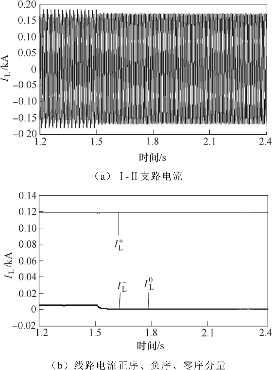
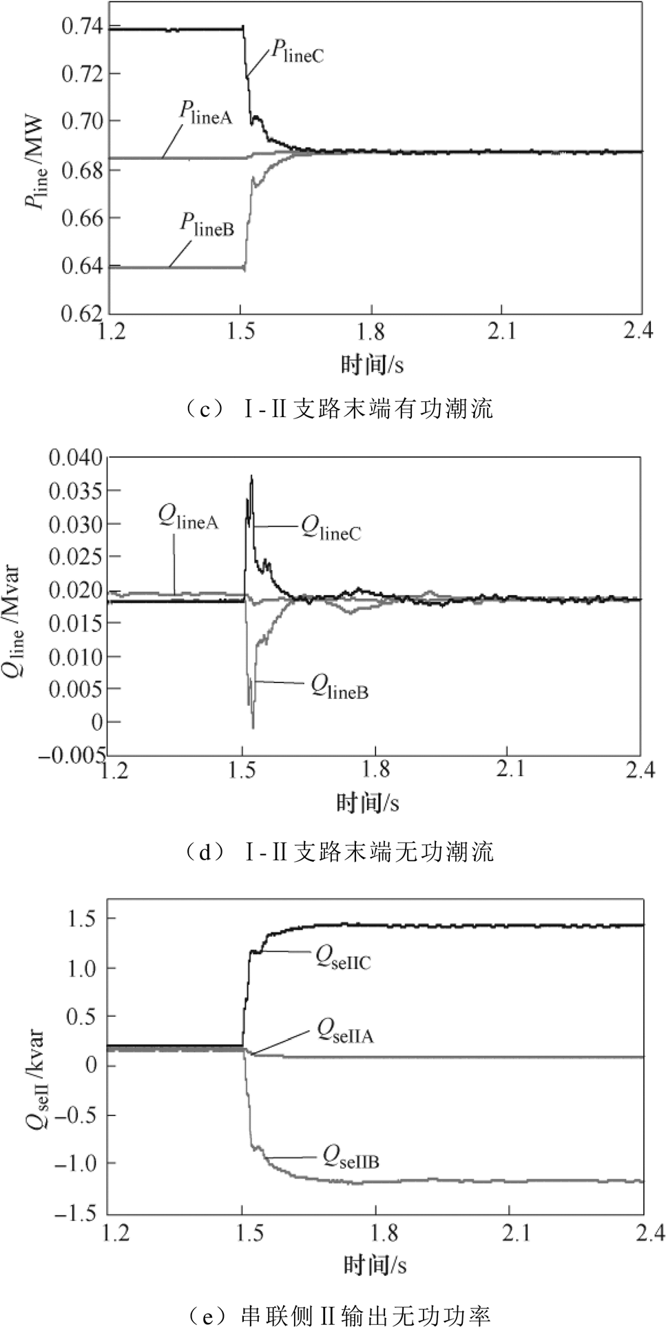
图15 补偿三相不对称仿真结果
Fig.15 Compensation results for three-phase asymmetry of distribution network
新能源电源投入会造成系统潮流的变化,但NDPFC的控制能有效促进新能源的消纳,其仿真结果如图16所示。线路末端潮流最终稳定于3.57+ j0.113Mvar,与用户侧负荷相匹配。线路首端输出有功潮流经0.2s由3.643MW降为3.171MW,减少量与新能源流向电网量近似相等。Ⅰ-Ⅱ支路电流变小,即线路潮流降低。
综上可见,NDPFC可通过控制线路末端潮流,在保障负荷需求的情况下,减小首端电源出力,以尽量多地利用新能源电源输出功率,有效促进新能源电源消纳。
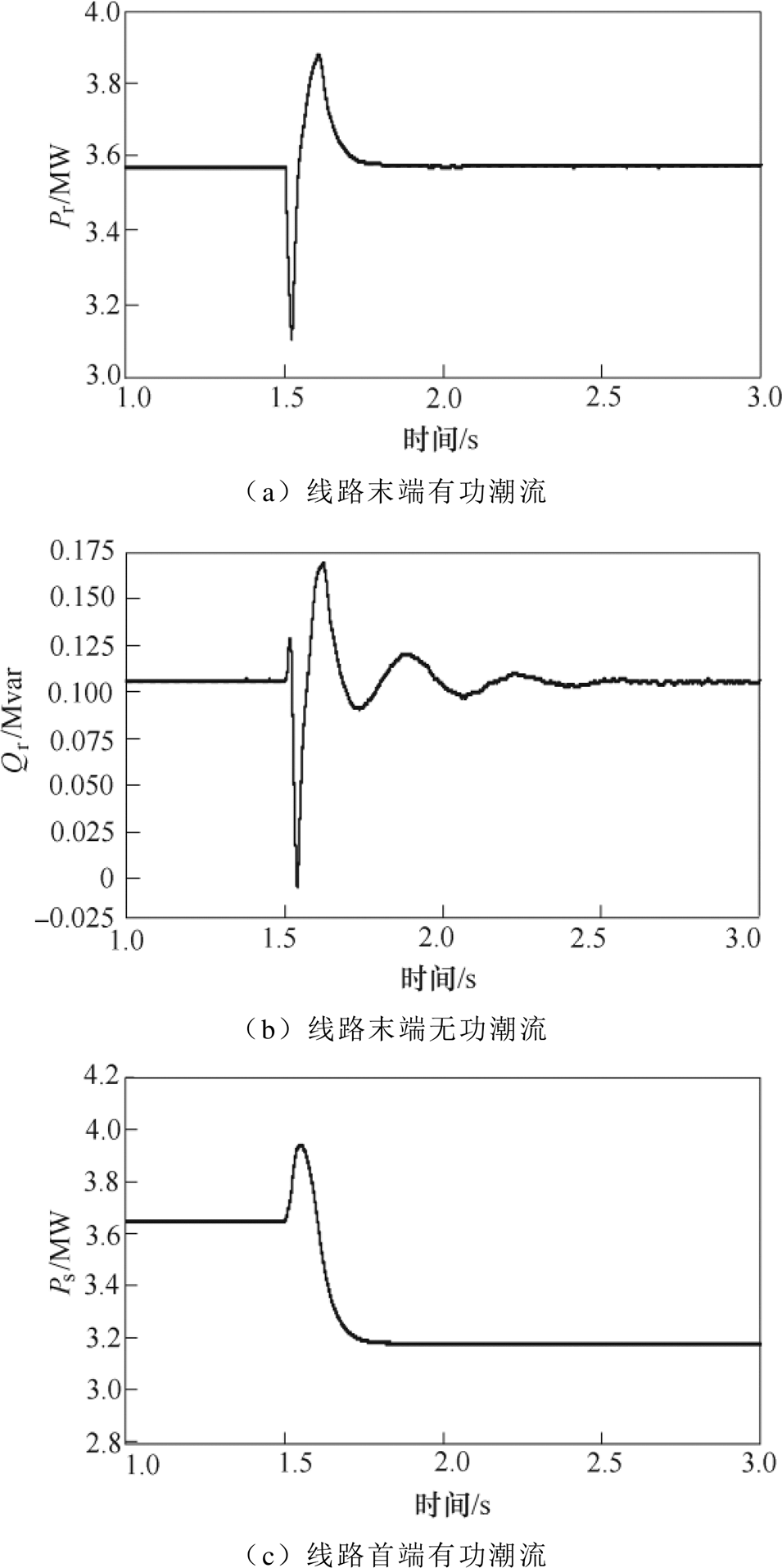

图16 促进新能源消纳仿真结果
Fig.16 Simulation results of promoting the consumption of renewable energy sources
本文提出了一种适用于配电网的分布式潮流控制器拓扑;应用典型配电网系统验证了其调节特性与调控范围;提出了串并联侧电磁暂态数学模型与高鲁棒性高精度的串联侧三环控制策略,通过NDPFC调控配电网综合潮流、补偿配电网三相不对称、促进新能源消纳的仿真实验,得出如下结论:
1)NDPFC可实现配电网综合潮流调控,解决潮流阻塞、系统潮流最优调控等问题。
2)NDPFC可通过改变每相出力,有效地改善因系统结构不对称而导致线路电流不对称的问题。
3)NDPFC可通过强制控制线路潮流,从而在无储能、负荷不可变的情况下减少首端电源出力,使得新能源电源完全输送至用户侧,促进新能源消纳。
参考文献
[1] 徐筝, 孙宏斌, 郭庆来. 综合需求响应研究综述及展望[J]. 中国电机工程学报, 2018, 38(24): 7194- 7205, 7446.
Xu Zheng, Sun Hongbin, Guo Qinglai. Review and prospect of integrated demand response[J]. Pro- ceedings of the CSEE, 2018, 38(24): 7194-7205, 7446.
[2] 缪惠宇, 梅飞, 张宸宇, 等. 基于虚拟阻抗的虚拟同步整流器三相不平衡控制策略[J]. 电工技术学报, 2019, 34(17): 3622-3630.
Miao Huiyu, Mei Fei, Zhang Chenyu, et al. Three phase unbalanced control strategy for virtual syn- chronous rectifier based on virtual impedance[J]. Transactions of China Electrotechnical Society, 2019, 34(17): 3622-3630.
[3] 肖湘宁, 廖坤玉, 唐松浩, 等. 配电网电力电子化的发展和超高次谐波新问题[J]. 电工技术学报, 2018, 33(4): 707-720.
Xiao Xiangning, Liao Kunyu, Tang Songhao, et al. Development of power-electronized distribution grids and the new supraharmonics issues[J]. Transactions of China Electrotechnical Society, 2018, 33(4): 707-720.
[4] 宋绍剑, 刘延扬, 刘斌, 等. 基于阻抗的电动汽车并网逆变器的稳定性分析[J]. 电机与控制学报, 2019, 23(4): 111-119.
Song Shaojian, Liu Yanyang, Liu Bin, et al. Impedance- based stability analysis of grid-connected inverter for electric vehicle[J]. Electric Machines and Control, 2019, 23(4): 111-119.
[5] 张旭, 王洪涛. 高比例可再生能源电力系统的输配协同优化调度方法[J]. 电力系统自动化, 2019, 43(3): 67-83, 115.
Zhang Xu, Wang Hongtao. Optimal dispatch method of transmission and distribution coordination for power systems with high proportion of renewable energy[J]. Automation of Electric Power Systems, 2019, 43(3): 67-83, 115.
[6] 毛安家, 马静, 蒯圣宇, 等. 高比例新能源替代常规电源后系统暂态稳定与电压稳定的演化机理[J]. 中国电机工程学报, 2020, 40(9): 2745-2756.
Mao Anjia, Ma Jing, Kuai Shengyu, et al. Evolution mechanism of transient and voltage stability for power system with high renewable penetration level[J]. Proceedings of the CSEE, 2020, 40(9): 2745-2756.
[7] 李建林, 袁晓冬, 郁正纲, 等. 利用储能系统提升电网电能质量研究综述[J]. 电力系统自动化, 2019, 43(8): 15-25.
Li Jianlin, Yuan Xiaodong, Yu Zhenggang, et al. Comments on power quality enhancement research for power grid by energy storage system[J]. Automation of Electric Power Systems, 2019, 43(8): 15-25.
[8] Elmetwaly A H, Eldesouky A A, Sallam A A. An adaptive D-FACTS for power quality enhancement in an isolated microgrid[J]. IEEE Access, 2020, 8: 57923-57942.
[9] 张茂松, 李家旺, 胡存刚, 等. 不平衡工况下链式D-STATCOM的控制策略[J]. 电机与控制学报, 2017, 21(12): 34-42, 50.
Zhang Maosong, Li Jiawang, Hu Cungang, et al. Control strategy of cascaded D-STATCOM under unbalanced conditions[J]. Electric Machines and Control, 2017, 21(12): 34-42, 50.
[10] 涂春鸣, 孙勇, 郭祺, 等. 适用于动态电压恢复器的最小能量柔性切换控制策略[J]. 电工技术学报, 2019, 34(14): 3035-3045.
Tu Chunming, Sun Yong, Guo Qi, et al. The minimum energy soft-switching control strategy for dynamic voltage restorer[J]. Transactions of China Electro- technical Society, 2019, 34(14): 3035-3045.
[11] Gao Chao, Liu Hui, Jiang Hao, et al. Research on the sub-synchronous oscillation in wind power connected to series compensated power system and its influencing factors[J]. CES Transactions on Electrical Machines and Systems, 2017, 1(3): 334-340.
[12] 高本锋, 王飞跃, 于弘洋, 等. 应用静止同步串联补偿器抑制风电次同步振荡的方法[J]. 电工技术学报, 2020, 35(6): 1346-1356.
Gao Benfeng, Wang Feiyue, Yu Hongyang, et al. The suppression method of wind power sub-synchronous oscillation using static synchronous series com- pensator[J]. Transactions of China Electrotechnical Society, 2020, 35(6): 1346-1356.
[13] Somayajula D, Crow M L. An integrated dynamic voltage restorer-ultracapacitor design for improving power quality of the distribution grid[J]. IEEE Transactions on Sustainable Energy, 2015, 6(2): 616-624.
[14] Wang Jiangfeng, Xing Yan, Wu Hongfei, et al. A novel dual-DC-port dynamic voltage restorer with reduced-rating integrated DC-DC converter for wide- range voltage SAG compensation[J]. IEEE Transa- ctions on Power Electronics, 2019, 34(8): 7437-7449.
[15] Cheung V S, Chung H S, Wang K, et al. Paralleling multiple static synchronous series compensators using daisy-chained transformers[J]. IEEE Transactions on Power Electronics, 2014, 29(6): 2764-2773.
[16] Brissette A, Maksimović D, Levron Y. Distributed series static compensator deployment using a line- arized transmission system model[J]. IEEE Transa- ctions on Power Delivery, 2015, 30(3): 1269-1277.
[17] 王倩, 施荣, 李宁. 分布式柔性交流输电系统的高效集群控制研究[J]. 电气传动, 2018, 48(9): 51-55.
Wang Qian, Shi Rong, Li Ning. Research on high efficiency cluster control of distributed flexible AC transmission system[J]. Electric Drive, 2018, 48(9): 51-55.
[18] Ghamsari M D, Firuzabad M F, Aminifar F, et al. Optimal distributed static series compensator placement for enhancing power system loadability and reliability[J]. IET Generation, Transmission & Distribution, 2015, 9(11): 1043-1050.
[19] 刘国静, 祁万春, 黄俊辉, 等. 统一潮流控制器研究综述[J]. 电力系统及其自动化学报, 2018, 30(12): 78-86.
Liu Guojing, Qi Wanchun, Huang Junhui, et al. Review of researches on unified power flow controller[J]. Proceedings of the CSU-EPSA, 2018, 30(12): 78-86.
[20] 李顺, 唐飞, 刘涤尘, 等. 分布式潮流控制器提升最大输电能力期望和供电可靠性的效能研究[J]. 电网技术, 2018, 42(5): 1573-1580.
Li Shun, Tang Fei, Liu Dichen, et al. Research on efficiency of distributed power flow controller to improve expected total transfer capability and power supply reliability[J]. Power System Technology, 2018, 42(5): 1573-1580.
[21] 任必兴, 杜文娟, 王海风. UPFC与系统的强动态交互对机电振荡模式的影响[J]. 电工技术学报, 2018, 33(11): 2520-2534.
Ren Bixing, Du Wenjuan, Wang Haifeng. Impact of strong dynamic interaction between UPFC and system on electromechanical oscillation mode[J]. Transa- ctions of China Electrotechnical Society, 2018, 33(11): 2520-2534.
[22] 满九方, 郝全睿, 高厚磊, 等. 基于MMC-UPFC对称分量控制的输电线路三相不平衡治理[J]. 中国电机工程学报, 2017, 37(24): 7143-7153, 7428.
Man Jiufang, Hao Quanrui, Gao Houlei, et al. Suppression of three-phase unbalanced current of transmission lines based on symmetrical component control of MMC-UPFC[J]. Proceedings of the CSEE, 2017, 37(24): 7143-7153, 7428.
[23] Tang Aihong, Shao Yunlu, Xu Qiushi, et al. Multi- objective coordination control of distributed power flow controller[J]. CSEE Journal of Power and Energy Systems, 2019, 5(3): 348-354.
[24] Tang Aihong, Shao Yunlu, Xu Qiushi, et al. Study on control method of distributed power flow controller[J]. IEEJ Transactions on Electrical and Electronic Engineering, 2019, 14(11): 1417-1623.
[25] 唐爱红, 高梦露, 黄涌, 等. 协调分布式潮流控制器串并联变流器能量交换的等效模型[J]. 电力系统自动化, 2018, 42(7): 30-36.
Tang Aihong, Gao Menglu, Huang Yong, et al. Equivalent model of coordinating energy exchange for series and shunt converters in distributed power flow controller[J]. Automation of Electric Power Systems, 2018, 42(7): 30-36.
[26] 陈勇, 曹伟炜, 柏彬, 等. MMC-UPFC单相接地故障下运行特性分析及整体保护策略设计[J]. 电工技术学报, 2019, 34(3): 599-610.
Chen Yong, Cao Weiwei, Bai Bin, et al. Operation characteristics analysis under single-phase grounding fault and overall protection scheme design of MMC- UPFC device[J]. Transactions of China Electro- technical Society, 2019, 34(3): 599-610.
A Novel Topology of Distributed Power Flow Controller for Distribution Network
Abstract In order to realize the transmission of the active power flow between the series side and the system, the conventional distributed power flow controller needs to interchange the power through the third harmonic current. Since the special △/YN and YN/△ transformers are required at both ends of the branch where the series side is located, the installation location of the distributed power flow controller in the distribution network is limited. Thus, a novel distributed power flow controller (NDPFC) for distribution network is proposed in this paper. The operation principle of the NDPFC is analyzed, and its power flow regulation range and regulation characteristics are verified by the typical distribution network system. In addition, the mathematical model of electromagnetic transient in series side of novel topology is studied, and a control strategy for series side Ⅰ and series side Ⅱ based on the three-loop control is proposed to improve the robustness and control accuracy. Finally, simulations in different distribution network scenarios verify that the NDPFC can realize the power flow regulation for the distribution network, compensate for three-phase imbalance, promote renewable energy consumption, and improve the power quality.
keywords:Novel distributed power flow controller (NDPFC), three-loop control, comprehensive power flow regulation, three-phase imbalance, consumption of renewable energy
DOI: 10.19595/j.cnki.1000-6753.tces.200744
中图分类号:TM761
唐爱红 女,1969年生,博士,教授,博士生导师,研究方向为智能电网运行与控制、柔性交直流输电技术。E-mail: tah@whut.edu.cn(通信作者)
翟晓辉 男,1996年生,硕士研究生,研究方向为柔性交直流输电技术。E-mail: zxh2019@whut.edu.cn
收稿日期 2020-06-30
改稿日期 2020-09-05
国家自然科学基金(51177114)和湖北省技术创新重大专项(2019AAA016)资助项目。
(编辑 陈 诚)