 对母线电压进行补偿,在维持母线电压稳定的同时,实现功率合理分配。文献[14]提出一种分布式下垂控制策略,将储能模块SOC与作差,通过在充放电模式下分别建立下垂系数与差值的一次函数关系,实现各模块间的SOC均衡。文献[15]通过建立下垂系数与差值的指数函数关系,保证母线电压跌落在合理范围内,实现了功率合理分配。文献[16]在上述策略基础上进行改进,提出一种SOC幂指数下垂控制策略,通过建立下垂系数与SOC差值的幂指数函数关系,提高了功率分配精度。
摘要 作为直流微电网中不可或缺的组成部分,分布式直流储能系统起着平抑系统能量波动、维持系统功率平衡的重要作用。为了提高储能系统工作的可靠性,该文对互联通信荷电状态(SOC)下垂控制策略进行深入研究。首先,对传统互联通信SOC下垂控制的系统性能及存在的问题进行分析,为之后控制策略的改进奠定基础;其次,提出改进互联通信SOC下垂控制策略,即在传统互联通信SOC下垂控制基础上引入变化系数;再次,通过对改进互联通信SOC下垂控制系统性能的分析,得到变化系数参数设计方法,在提高系统功率收敛速度的同时,限制功率输出最大值,从而提高系统可靠性;最后,对由两台储能模块构成的储能系统进行仿真和实验,实验结果验证了改进策略的快速性及对输出功率的限制。
关键词:分布式储能系统 互联通信 荷电状态下垂控制 功率均衡
随着光伏、风电等分布式发电渗透率的提高,分布式直流储能系统由于其突出的优势,被广泛应用于微电网以稳定直流母线电压和提高系统可靠 性[1-2],同时通过储能系统吸收或释放功率以起到“削峰填谷”的作用。在分布式直流储能系统中,多台储能模块通过双向DC-DC变换器并联于直流母线[3-4],由于各储能模块荷电状态(State Of Charge, SOC)存在差异,为了保证系统安全稳定运行,常采用SOC下垂控制来实现功率在各储能模块之间的合理分配[5-7]。目前,SOC下垂控制主要分为无互联通信SOC下垂控制和有互联通信SOC下垂控制两种。
文献[8-9]提出一种两象限SOC下垂控制策略,通过构建下垂系数与SOC的n次幂成反比的关系从而实现功率合理分配,但在SOC较小时存在电压跌落较大的问题。为了解决该问题,文献[10]在两象限SOC下垂控制基础上,提出直流母线电压二次控制策略,在提高系统稳定性的同时,增加了系统复杂性。文献[11]提出一种基于SOC自适应下垂系数协同控制策略,在功率按SOC合理分配的前提下,减小母线电压跌落值。文献[12]建立下垂系数与SOC的指数函数关系,在实现功率合理分配的同时,保证母线电压跌落在合理范围之内,从而提高了系统可靠性。以上无互联通信SOC下垂控制策略具有控制简单和可靠性高等特点,但是存在功率均衡速度慢的缺点。
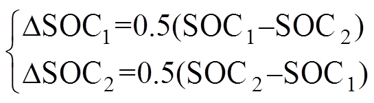
为了提高响应速度和功率分配精度,采用互联通信SOC下垂控制策略。文献[13]提出一种双模式下垂的SOC均衡控制策略,通过储能模块间的SOC差值确定系统工作模式,并根据各储能模块SOC均值对母线电压进行补偿,在维持母线电压稳定的同时,实现功率合理分配。文献[14]提出一种分布式下垂控制策略,将储能模块SOC与作差,通过在充放电模式下分别建立下垂系数与差值的一次函数关系,实现各模块间的SOC均衡。文献[15]通过建立下垂系数与差值的指数函数关系,保证母线电压跌落在合理范围内,实现了功率合理分配。文献[16]在上述策略基础上进行改进,提出一种SOC幂指数下垂控制策略,通过建立下垂系数与SOC差值的幂指数函数关系,提高了功率分配精度。
上述互联通信SOC下垂控制策略均可实现储能模块间SOC均衡,并经过不断改进以提高系统的可靠性和控制精度,但仍存在SOC均衡速度较慢的缺点,且在储能模块SOC差值较大时,存在储能模块输出功率超出其额定功率的现象。因此,本文在传统互联通信SOC指数下垂控制策略基础上,引入变化系数,在实现功率合理分配的同时,限制各储能模块最大输出功率,保证其在工程允许范围内,并加快了系统整体收敛速度,使各模块输出功率更快地趋于均衡。
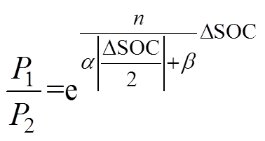
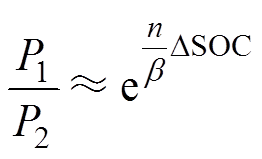
传统互联通信SOC指数下垂控制表达式为
 (1)
(1)式中,下标 为储能模块序号;
 为第台储能模块下垂控制输出电压参考信号;
 为直流母线电压参考信号;
 为第台储能模块输出功率;
 为第台储能模块的SOC下垂系数,表达式为
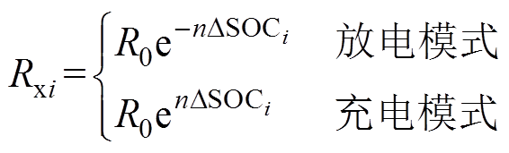 (2)
(2)
式中, 为初始下垂系数;n为均衡速度调节因子;
 为第台储能模块剩余容量
 与所有储能模块SOC平均值的差值,其表达式为
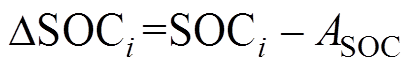 (3)
(3)其中
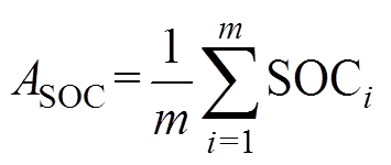 (4)
(4)
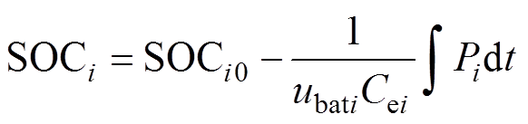 (5)
(5)式中, 为第台蓄电池初始剩余容量;
 为第台蓄电池总容量;
 为第台蓄电池输出电压;m为储能模块总个数。
本文以两台功率相等的储能模块为例进行分析,其等效电路模型如图1所示,图中, 分别为第1台和第2台储能模块直流母线电流,
 为等效线路阻抗,
 为直流负载电阻,
 为直流母线电压。由于充放电模式下功率均衡机理相似,为了简化分析过程,本文以
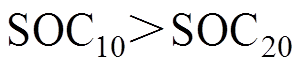 为例,对放电模式下的SOC下垂控制及功率均衡原理进行分析。
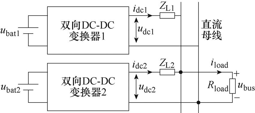
图1 两台储能模块并联的等效电路模型
Fig.1 Equivalent circuit model for parallel connection of two energy storage modules
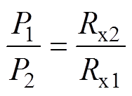
由于等效线路阻抗很小,忽略线路阻抗影响,可近似认为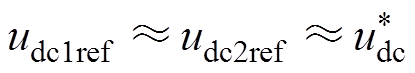 ,代入式(1)可得储能模块输出功率比值与下垂系数关系 式为
 (6)
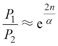
(6)将式(1)代入式(6),可得传统互联通信SOC指数下垂控制的输出功率比值为
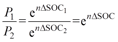 (7)
(7)
式中, 为储能模块1与储能模块2的SOC差值,其表达式为
 (8)
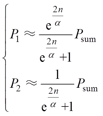
(8)根据式(7),可得储能模块的输出功率分别为
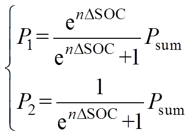 (9)
(9)
式中, 为两个储能模块输出功率之和。
将式(4)代入式(3)中,则 和
和 又可写为
又可写为
 (10)
(10)根据式(8)及式(10),可得和与的关系式为
 (11)
(11)
在分布式储能系统中,为保证蓄电池正常工作,延长使用寿命,蓄电池SOC的工作范围为[0.3, 0.9][17],则工作范围为[0.3, 0.9], 的工作范围为
 ,的工作范围为
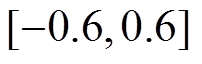 。
。
根据式(7),可得在不同调节因子n下,传统互联通信SOC下垂控制的功率比值与的特性曲线如图2所示。由图2可知,储能模块间的功率分配及均衡速度由和n值决定。在相同n值下,随着功率均衡的调节,减小,储能模块间输出功率比值减小,储能系统的SOC均衡速度变慢,当逐渐趋近于0时,储能模块间输出功率的差值较小且均衡速度很慢。在相同值下,n值越大,储能系统SOC均衡速度越快,同时功率比值越大,可能导致储能模块输出功率远远超出其额定功率,从而导致电路设计难度及成本增加。
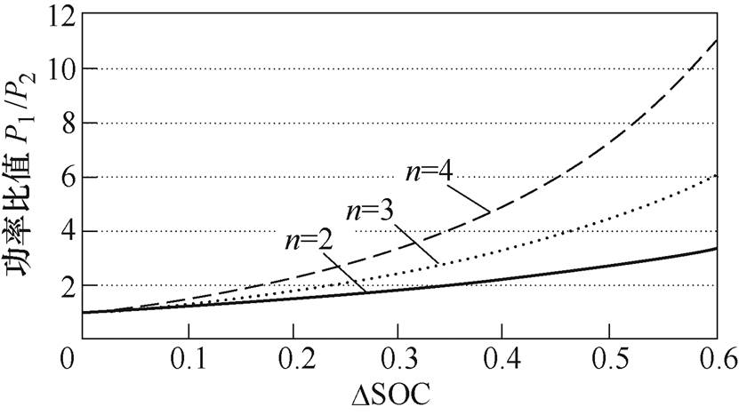
图2 功率比值与DSOC的特性曲线
Fig.2 The characteristic curves of power ratio and DSOC
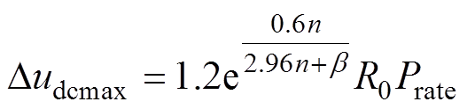
直流母线电压跌落最大值 等于下垂系数最大值
 与储能模块输出最大功率
 的乘积,即
的乘积,即
 (12)
(12) 对应于
对应于 和
和 ,将其代入式(9),整理可得储能模块1的输出最大功率为
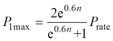 (13)
(13)
式中,Prate为额定功率。
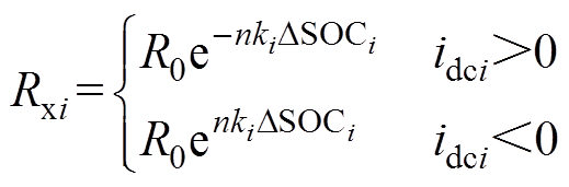
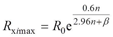
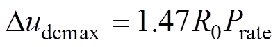
放电模式的下垂系数为单调递减函数,因此, 对应于最大SOC下垂系数,则传统互联通信SOC下垂控制的表达式为
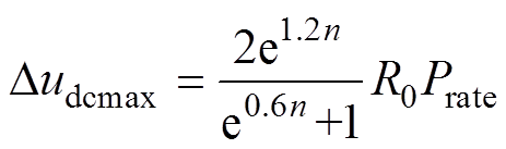 (14)
(14) 为了简化分析过程,令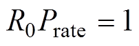 ,则传统互联通信SOC下垂控制在不同n值下直流母线电压跌落最大值波形如图3所示,随着n值的增大而增大,严重时会导致直流母线电压跌落超过允许范围,从而影响系统的稳定性。
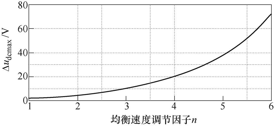
图3 不同n值下Dudcmax的波形
Fig.3 Waveform of Dudcmax under different n values
综上所述,传统互联通信SOC指数下垂控制存在如下问题:①SOC均衡速度慢;②储能模块输出功率远远超出额定功率;③直流母线电压跌落最大值较大。
为了解决传统互联通信SOC指数下垂控制策略存在的问题,本文在其控制策略基础上引入变化系数以修正下垂系数与SOC之间的函数关系,在保证输出功率合理分配的同时,限制各储能模块最大输出功率并加快各模块输出功率的整体均衡速度,同时大大降低直流母线电压跌落最大值,提高系统稳定性和可靠性。
改进互联通信SOC指数下垂控制的下垂系数表达式为
 (15)
(15)其中,变化系数 的表达式为
的表达式为
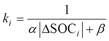 (16)
(16)
式中, 与
与 均为常数。
均为常数。
在变化系数 中,
中, 分阶段作用,作用原理具体如下:
(1)当 趋近于0时,变化系数近似为
 。为了起到加快功率均衡速度的目的,的取值要求为
 ,即
,即 。
。
(2)当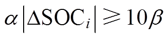 时,可忽略的影响,变化系数近似为
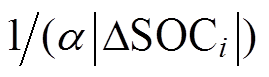 ,通过合理设置值,可限制输出功率比值最大值,从而限制输出功率最大值,保证储能模块功率在工程允许范围内。
将式(15)代入式(6),可得改进互联通信SOC指数下垂控制的输出功率比值为
 (17)
(17)将式(11)代入式(17),整理可得输出功率比值与的关系式为
 (18)
(18)
根据式(7)及式(18),可得改进前后两种SOC下垂控制策略的功率比值特性曲线对比如图4所示。
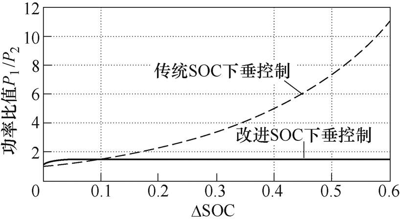
图4 两种控制策略下功率比值特性曲线对比
Fig.4 The characteristic curves comparison of power ratio under two control strategies
由图4可知,改进SOC指数下垂控制在值较大时,输出功率比值趋于恒定,加速因子对输出功率起到限制作用;在趋近于0时,起到放大作用,加快了系统功率均衡速度。
根据式(1)及图1建立储能模块1的SOC下垂控制结构如图5所示,其中,SOC估算等效为惯性环节, 为惯性时间常数,输出电压闭环传递函数
 可近似为1,
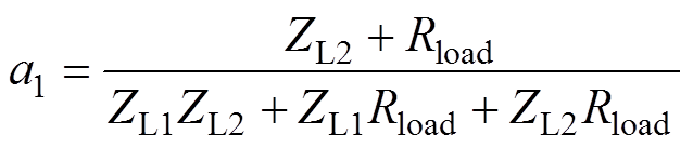
 为功率低通滤波时间常数。系数
 与
与 、
、 和
和 相关。
相关。
忽略扰动项 的影响,根据图5推导出储能模块1的SOC下垂控制闭环传递函数
 为
为
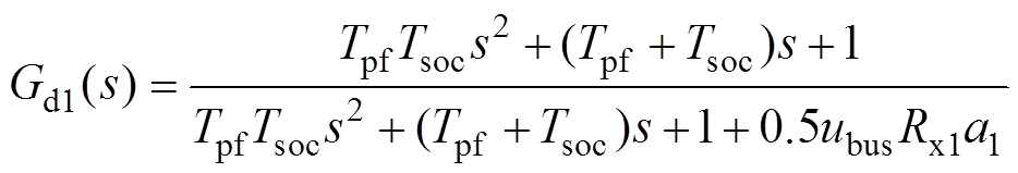 (19)
(19)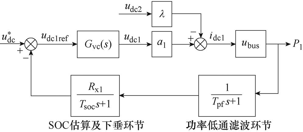
图5 SOC下垂控制结构
Fig.5 SOC droop control structure
其中
 (20)
(20)根据式(19),列出劳斯阵列为
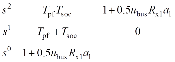 (21)
(21)
由于 ,即劳斯阵列第一列系数全为正值,SOC下垂控制系统稳定,即控制系统稳定性基本不受下垂系数影响。
 设计方法
设计方法根据式(18),在 且取不同值时,输出功率比值与
 的特性曲线如图6所示。储能模块输出功率比值随着
 的增大逐渐增大并趋于恒定,即为功率恒值区。在功率恒值区,储能模块的输出功率比值可近似如式(22)所示,即通过设计参数,可限制最大输出功率,从而保证储能模块功率在设计范围内运行。
 (22)
(22)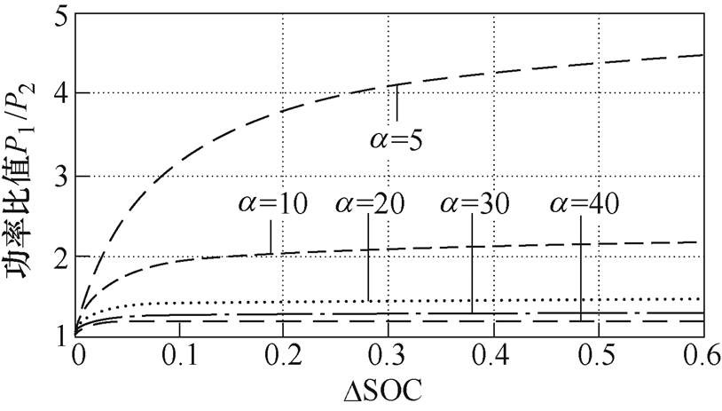
图6 不同 值下功率比值与
 的特性曲线
的特性曲线
Fig.6 The characteristic curves of power ratio and under different values
从图6和式(22)可知,在相同情况下,储能模块输出功率比值与值成反比,即值越小,
输出功率差值越大,系统收敛速度越快。从输出功率限制与系统收敛速度两方面综合考虑,在设计参数时,应在满足输出功率限制的基础上尽量取其最小值。
根据式(22),在功率恒值区时储能模块间的功率分配近似如式(23)所示,储能多的模块功率分配大于储能少的模块,通过对前者输出功率表达式中参数进行设计,可限制其输出功率上限,使储能模块工作在工程允许范围内。
 (23)
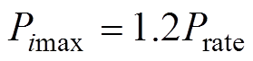
(23)按工程设计要求,以各模块SOC均衡时输出功率的1.2倍为储能模块输出功率上限[18],由式(23)可以推导出参数取值范围为
 (24)
(24)
为了达到限制输出功率最大值和提高系统收敛速度的目的,参数的选值为
 (25)
(25) 设计
设计改进SOC下垂控制中引入变化系数,使得在SOC的差值较小时,由于 ,>1,变化系数对功率比值起到放大作用。相比于传统SOC下垂控制,在趋于0时,改进SOC下垂控制增大了储能模块间输出功率比值,使储能多的模块多放电,储能少的模块少放电,从而起到加快收敛速度的效果,则加速区间为
 (26)
(26)在加速区间内,输出功率比值近似为
 (27)
(27)
由式(26)可知,储能系统加速区间随的减小而增大。在取不同值时,输出功率比值与的特性曲线如图7所示。随着各储能模块的SOC趋于一致,在相同的情况下,储能模块输出功率比值与值成反比,即值越小,系统收敛速度越快,但当取值过小时,其特性与符号函数特性相似,因此,系统出现抖振现象。综合考虑系统功率收敛快速性和抗抖振性,取值应在保证系统抗抖振的前提下,尽量取较小值。
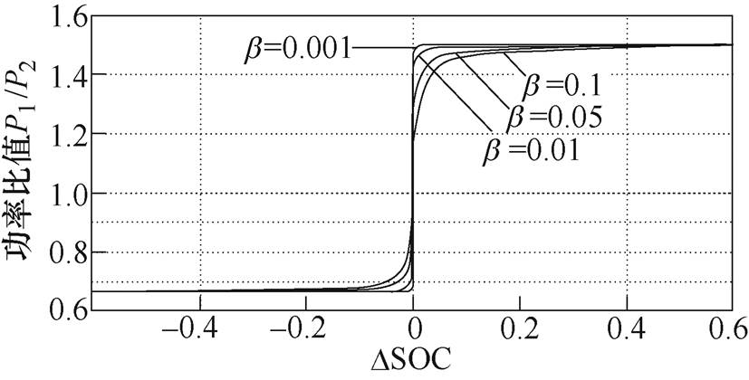
图7 不同b 值下功率比值与DSOC的特性曲线
Fig.7 The characteristic curves of power ratio and under different b values
根据功率限制要求,储能模块输出最大功率为
 (28)
(28)放电模式的下垂系数为单调递减函数,因此,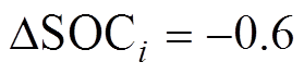 对应于最大SOC下垂系数,且按式(25)设计参数,得下垂系数最大值为
 (29)
(29)
改进互联通信SOC指数下垂控制的 表达式为
表达式为
 (30)
(30)由于 ,因此,可以忽略对的影响,则可近似为
 (31)
(31)
从式(31)可知,在改进互联通信SOC指数下垂控制中,基本不受 值影响。
值影响。
图8为不同均衡速度调节因子n下,改进前后直流母线电压允许跌落最大值对比波形。由图8可知,相对于传统SOC下垂控制,改进SOC下垂控制中直流母线电压跌落最大值 得到大幅度减小,因此,无需母线电压二次控制,增加了系统可靠性。
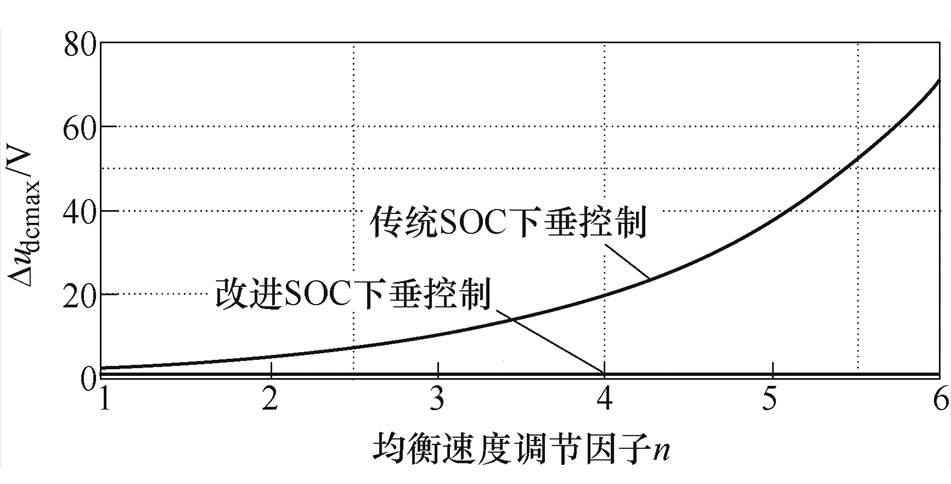
图8 两种控制策略下Dudcmax对比波形
Fig.8 Comparison waveforms of Dudcmax under two control strategies
建立由两台储能模块构成的分布式储能系统,其中,变换器采用悬浮交错并联双向DC-DC变换器,而改进互联通信SOC下垂控制框图如图9所示,两个储能模块控制策略相同。仿真参数具体如下:蓄电池电压为200V,直流母线电压为1 200V,储能单元容量为1.5A·h,额定功率 ,直流负
,直流负
载功率10kW。初始放电下垂系数 。
。
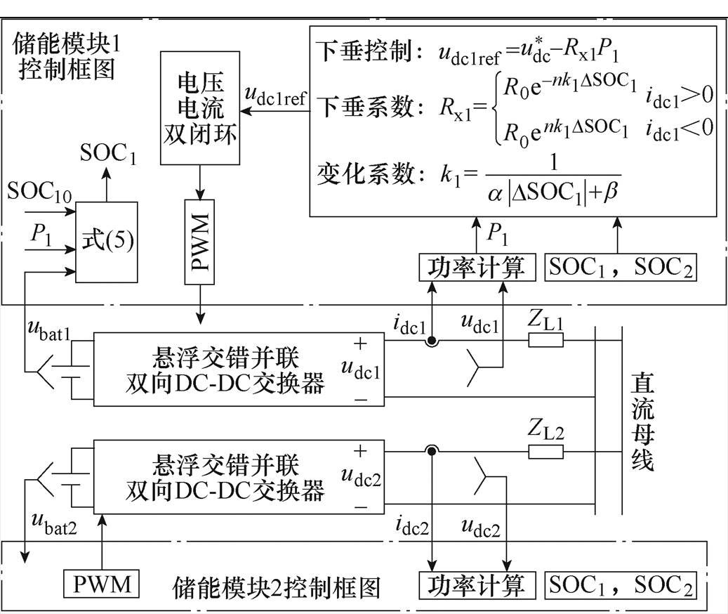
图9 改进互联通信SOC下垂控制框图
Fig.9 Block diagram of improved interconnected communication SOC droop control
为了验证改进互联通信SOC下垂控制在放电模式下的可行性和有效性,分别对采用传统和改进互联通信SOC下垂控制策略的系统进行仿真,仿真结果如图10~图12所示,其中, 和
和 。
。
图10为不同n值下采有传统互联通信SOC下垂控制的功率及SOC仿真波形。由图可知,该控制方法可以实现直流母线功率在储能模块间的合理分配,调节因子n越大,功率收敛速度越快,但同时输出功率将超出功率上限值( ),从而降低了系统可靠性;反之,调节因子n越小,输出功率运行于允许范围内,但功率收敛速度慢。
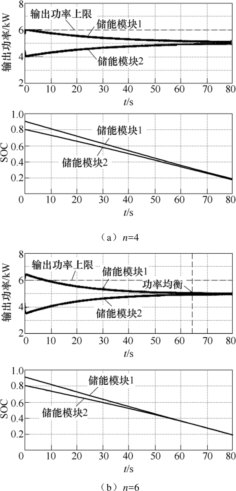
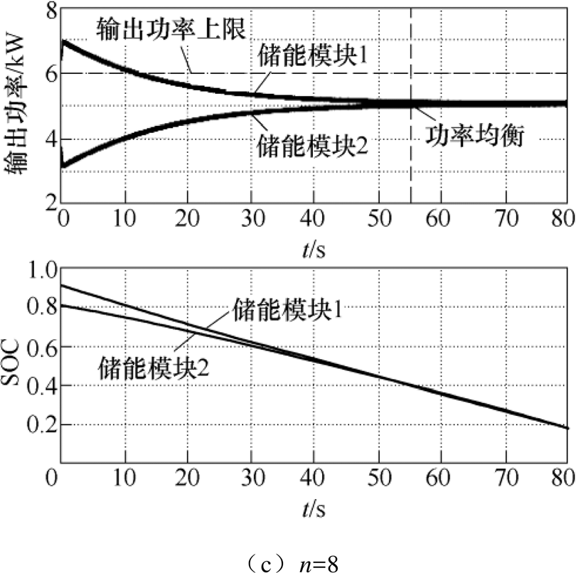
图10 不同n值下传统SOC下垂控制的功率及SOC仿真波形
Fig.10 Power and SOC simulation waveforms of traditional SOC droop control under different n values
图11 n=6时改进SOC下垂控制功率及SOC仿真波形
Fig.11 Power and SOC simulation waveforms of improved SOC droop control when n=6
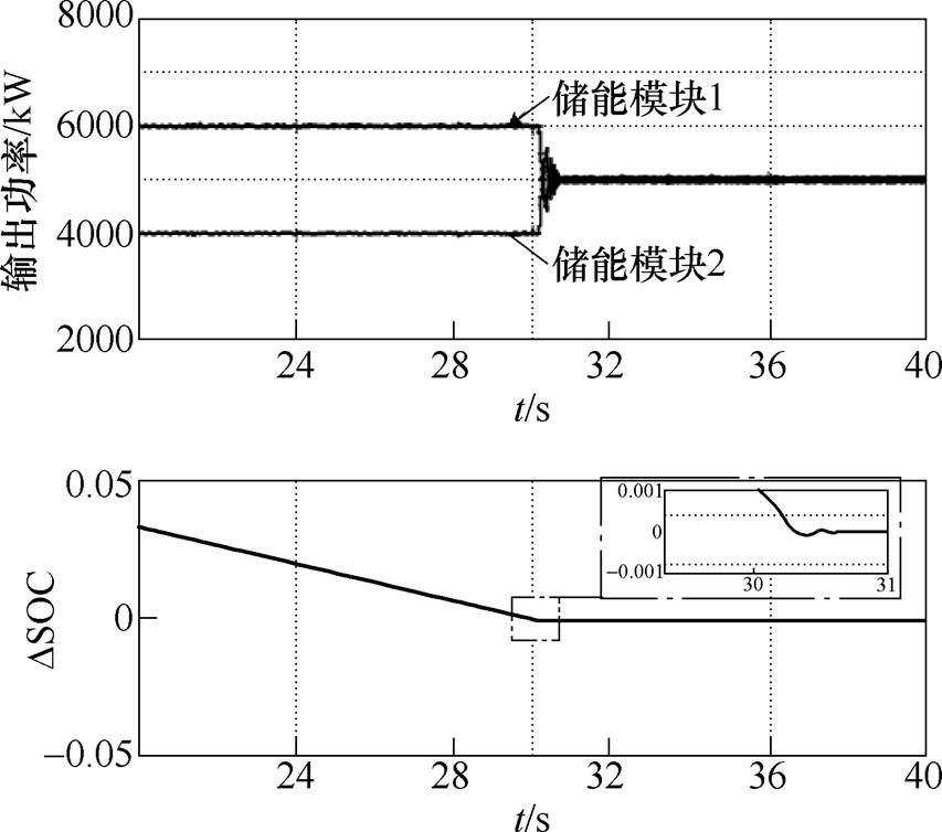
图12 改进SOC下垂控制波形
Fig.12 Waveforms of improved SOC droop control
不同变化系数下改进互联通信SOC下垂控制功率及SOC仿真波形如图11所示,其中,调节因子 。由图11a可知,按式(25)设计参数
 的值,得
的值,得 ,在额定负载情况下,输出功率最大值受限,等于功率上限值
 。由图11b所示,增大值,最大输出功率减小,同时SOC均衡速度越慢。与图11a相比,在图11c中输出功率最大值等于,但由于
 值减小,SOC均衡速度加快。
当,和 时,改进SOC下垂控制仿真波形如图12所示,系统稳定运行。与图11c相比,SOC均衡速度加快,但在
 较小处,和输出功率都出现抖动现象,从而降低了输电质量。
当,和 时,改进SOC下垂控制的充电模式仿真波形如图13所示,其中,
 和
和 。由图可知,模块输出功率和SOC的均衡性能与放电模式相同,从而验证了上述理论分析在充电模式的有效性。
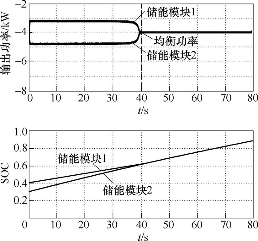
图13 改进SOC下垂控制的充电模式仿真波形
Fig.13 Charging mode simulation waveforms of improved SOC droop control
改进SOC下垂控制策略的直流母线电压仿真波形如图14所示,直流母线电压稳定于1 200V,其直流母线电压跌落最大值很小,为1V左右,大大提高了直流母线电压的稳定性。
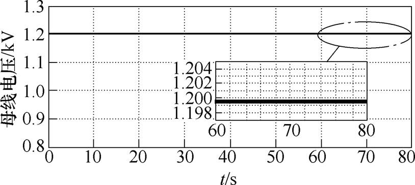
图14 直流母线电压仿真波形
Fig.14 Simulation waveforms of DC bus voltage
搭建由两台储能模块构成的分布式储能系统实验平台,其中,变换器采用悬浮交错并联双向DC-DC变换器,实物如图15所示。通过DSP(TMS320F28335)数字控制电路实现并联运行的两个储能模块的输出功率控制。实验参数具体如下:蓄电池电压为40V,直流母线电压为160V,储能单元容量为1.5A·h,母
线负载为50W。初始放电下垂系数,和。

图15 双向DC-DC变换器实物
Fig.15 Bidirectional DC-DC converter physical image
图16和图17分别为传统和改进SOC下垂控制的放电模式实验波形,其中, 和
和 。从图中可以看出,两种控制都达到了功率均分的目的,但改进SOC下垂控制限制了输出功率最大值,同时加快了系统功率和SOC收敛速度,验证了放电模式理论分析的正确性。
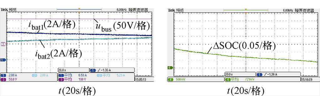
图16 n=6时传统SOC下垂控制的放电模式实验波形
Fig.16 Discharging mode experimental waveforms of traditional SOC droop control with n=6
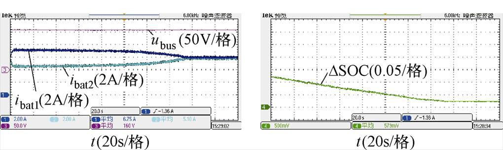
图17 n=6时改进SOC下垂控制的放电模式实验波形
Fig.17 Discharging mode experimental waveforms of improved SOC droop control with n=6
图18和图19分别为传统和改进SOC下垂控制的充电模式实验波形,其中,和。模块输出功率和SOC的均衡性能与放电模式相同,从而验证了上述理论分析在充电模式的有效性。
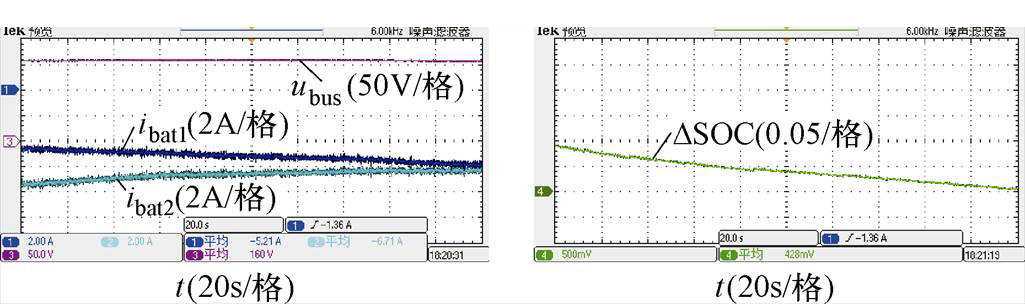
图18 n=6时传统SOC下垂控制的充电模式实验波形
Fig.18 Charging mode experimental waveforms of traditional SOC droop control with n=6
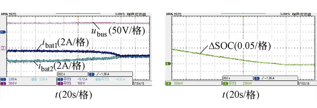
图19 n=6时改进SOC下垂控制的充电模式实验波形
Fig.19 Charging mode experimental waveforms of improved SOC droop control with n=6
本文提出一种改进互联通信SOC下垂控制策略,通过在传统互联通信SOC下垂控制基础上引入变化系数以修正下垂系数与SOC之间的函数关系,从而改善了系统性能,并通过仿真和实验验证了改进控制方案的可行性,得出以下结论:
1)当 值较大时,变化系数
 近似为
近似为 ,储能模块间的功率比值存在最大值。令
 ,以保证储能模块工作在工程允许范围内,增加了系统的可靠性。
2)当趋近于0时,变化系数近似为 ,加快了功率和SOC收敛速度。综合考虑,取值应在保证系统抗抖振前提下,尽量取较小值。
3)大大降低了直流母线电压跌落最大值,无需母线电压二次控制,增加了系统的可靠性。
参考文献
[1] 郭伟, 赵洪山. 基于事件触发机制的直流微电网多混合储能系统分层协调控制方法[J]. 电工技术学报, 2020, 35(5): 1140-1148.
Guo Wei, Zhao Hongshan. Coordinated control method of multiple hybrid energy storage systemin DC microgrid based on event-triggered mechanism[J]. Transactions of China Electrotechnical Society, 2020, 35(5): 1140-1148.
[2] 毕恺韬, 孙力, 安群涛, 等. 基于模块化多电平直流变换器的储能系统分布式能量均衡控制策略[J]. 电工技术学报, 2018, 33(16): 3811-3821.
Bi Kaitao, Sun Li, An Quntao, et al. Distributed energy balancing control strategy for energy storage system based on modular multilevel DC-DC con- verter[J]. Transactions of China Electrotechnical Society, 2018, 33(16): 3811-3821.
[3] Marcelino F L F, Sathler H H, Silva W W A G, et al. A comparative study of droop compensation functions for state-of-charge based adaptive droop control for distributed energy storage systems[C]//IEEE 8th International Symposium on Power Electronics for Distributed Generation Systems (PEDG), Floriano- polis, Brazil, 2017: 1-5.
[4] 张辉, 梁誉馨, 孙凯, 等. 直流微电网中多端口隔离型DC-DC变换器的改进虚拟电容控制策略[J]. 电工技术学报, 2021, 36(2): 292-304.
Zhang Hui, Liang Yuxin, Sun Kai, et al. Improved virtual capacitor control strategy of multi-port isolated DC-DC converter in DC microgrid[J]. Transactions of China Electrotechnical Society, 2021, 36(2): 292-304.
[5] Liu Guangyuan, Mattavelli P, Saggini S. Resistive- capacitive output impedance shaping for droop- controlled converters in DC microgrids with reduced output capacitance[J]. IEEE Transactions on Power Electronics, 2020, 35(6): 6501-6511.
[6] Shi Guangze, Han Hua, Sun Yao, et al. A decentra- lized SOC balancing method for cascaded-type energy storage system[J]. IEEE Transactions on Industrial Electronics, 2021, 68(3): 2321-2333.
[7] 张继元, 舒杰, 宁佳, 等. 考虑SOC自均衡的光储独立微电网协调控制[J]. 电工技术学报, 2018, 33(增刊2): 527-535.
Zhang Jiyuan, Shu Jie, Ning Jia, et al. Coordinated control for PV/storage hybrid islanded microgrid considering SOC balancing[J]. Transactions of China Electrotechnical Society, 2018, 33(S2): 527-535.
[8] Lu Xiaonan, Sun Kai, Guerrero J M, et al. State- of-charge balance using adaptive droop control for distributed energy storage systems in DC microgrid applications[J]. IEEE Transactions on Industrial Electronics, 2014, 61(6): 2804-2815.
[9] Han Ying, Li Qi, Wang Tianhong, et al. Multisource coordination energy management strategy based on SOC consensus for a PEMFC-battery-supercapacitor hybrid tramway[J]. IEEE Transactions on Vehicular Technology, 2018, 67(1): 296-303.
[10] Lu Xiaonan, Sun Kai, Guerrero J M, et al. Double- quadrant state-of-charge-based droop control method for distributed energy storage systems in autonomous DC microgrids[J]. IEEE Transactions on Smart Grid, 2015, 6(1): 147-157.
[11] 邓诗蕾, 王明渝. 直流微电网潮流控制器与分布式储能协同控制策略[J]. 电力系统保护与控制, 2018, 46(24): 40-46.
Deng Shilei, Wang Mingyu. Cooperative control strategy of DC microgrid power flow controller and distributed energy storage system[J]. Power System Protection and Control, 2018, 46(24): 40-46.
[12] 梁梦娜. 储能系统双极性直流母线功率均衡控制及负荷分配控制[D]. 秦皇岛: 燕山大学, 2018.
[13] 吴青峰, 孙孝峰, 郝彦丛, 等. 微电网储能系统SOC平衡和电压频率恢复研究[J]. 太阳能学报, 2018, 39(6): 1743-1751.
Wu Qingfeng, Sun Xiaofeng, Hao Yancong, et al. Research of SOC balance and voltage frequence recovery of microgrid energy storage system[J]. Acta Energiae Solaris Sinica, 2018, 39(6): 1743-1751.
[14] 吴青峰, 孙孝峰, 王雅楠, 等. 基于分布式下垂控制的微电网分布式储能系统SOC平衡策略[J]. 电工技术学报, 2018, 33(6): 1247-1256.
Wu Qingfeng, Sun Xiaofeng, Wang Yanan, et al. A distributed control strategy for SOC balancing of distributed energy storage systems in microgrid[J]. Transactions of China Electrotechnical Society, 2018, 33(6): 1247-1256.
[15] Oliveira T R, Silva W W A G, Donoso-garcia P F. Distributed secondary level control for energy storage management in DC microgrids[J]. IEEE Transactions on Smart Grid, 2017, 8(6): 2597-2607.
[16] 李鹏程, 张纯江, 袁然然, 等. 改进SOC下垂控制的分布式储能系统负荷电流分配方法[J]. 中国电机工程学报, 2017, 37(13): 3746-3754.
Li Pengcheng, Zhang Chunjiang, Yuan Ranran, et al. Load current sharing method of distributed energy storage systems by improved SOC drooping control[J]. Proceedings of the CSEE, 2017, 37(13): 3746-3754.
[17] 刘世林, 文劲宇, 孙海顺. 适用于风电功率调控的复合储能系统及其控制策略[J]. 中国电机工程学报, 2015, 35(1): 95-102.
Liu Shilin, Wen Jinyu, Sun Haishun. Hybrid energy storage system and its control strategies intended for wind power conditioning[J]. Proceedings of the CSEE, 2015, 35(1): 95-102.
[18] 王兆安, 刘进军. 电力电子技术[M]. 5版. 北京: 机械工业出版社, 2016.
Improved Interconnected Communication State of Charge Droop Control and Power Balance Optimization
Abstract As an integral part of the DC microgrid, the distributed energy storage system plays an important role in suppressing system energy fluctuations and maintaining system power balance. In order to improve the reliability of the energy storage system, the interconnected communication state of charge (SOC) droop control strategy is studied. Firstly, the system performance and existing problems of the traditional interconnected communication SOC droop control are analyzed. Secondly, the improved interconnected communication SOC droop control strategy is proposed, that is, a variation coefficient is introduced on the basis of the traditional interconnected communication SOC droop control. Thirdly, through the analysis of the system performance of the improved interconnected communication SOC droop control, the design method of variation coefficient parameters is obtained, which not only improves the power convergence speed of the system, but also limits the maximum power output, thereby improving the reliability of the system. Finally, the energy storage system consisting of two energy storage modules is simulated and tested. The results verify the rapidity of the improved strategy and its limitation on the output power.
keywords:Distributed energy storage system, interconnected communication, state of charge droop control, power balance
DOI: 10.19595/j.cnki.1000-6753.tces.L90461
中图分类号:TM464
柴秀慧 女,1984年生,讲师,硕士生导师,研究方向为风力发电变流器及控制技术和储能系统功率流控制等。E-mail: caixiuhuihb@126.com
张纯江 男,1961年生,教授,博士生导师,研究方向为可再生能源分布式发电及控制技术等。E-mail: zhangcj@ysu.edu.cn(通信作者)
收稿日期 2020-07-11
改稿日期 2020-10-01
国家自然科学基金项目(51877187)和河北省博士后科研项目(B2019003024)资助。
(编辑 陈 诚)